Thinking ahead (again), it is likely that I will want to carry something, maybe sand ladders, on the side of the vehicle. Off side only as there is a window on the near side.
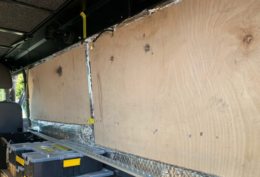
Given that work on the inside will be carried out soon, I need to mount Cargo Rail (1805 light duty tracking) now. Once the interior panels are fitted, I will not be able to access the ends of the bolts to secure them.
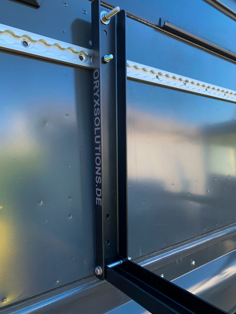
I found some very nice Aluminium Brackets from Oryx Solutions in Germany which fold down, so you could use a mounted sand ladder or recovery track as a make shift table. These were ordered as they would determine the gap between cargo rails.
Oryx make some great products for all sorts of vehicles and if I had not wanted to make use of the cabinets that I already had, then their range of interior fittings would have been very tempting; maybe next time!
The brackets are beautifully made but very expensive, especially when you factor in import duty. The actual cargo rail and fittings are not exactly budget purchases either!
Fitting Cargo Rail
Having the ply lining inside, made a very secure way of bolting the Cargo Rail on the vehicle.
This was one of those jobs that you cannot do on your own, so I enlisted the help of my Dad to hold the top rail whilst the holes were drilled and the rail bolted into place – stainless steel with lots of Sikaflex.
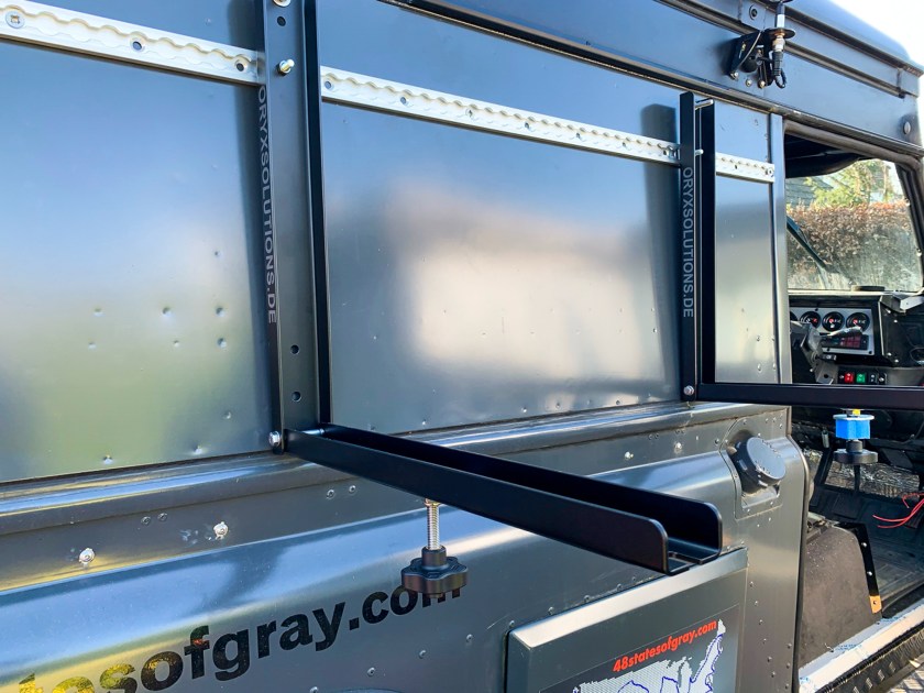
We then used the brackets to correctly position the bottom rail and repeated the procedure.
It was then simple to mount the brackets . I have other fittings, so can use the rail for other items as well, in the future.
I ordered some recovery boards, that I suspect we will only use for levelling the vehicle on camp sites and for getting out of the odd slippy situation. If we were considering serious off reading then I would go for the Matrix product.
Cargo Rail fitted.
The fittings in the brackets that secure the load, have very clever locks built in – great security – you get what you pay for.
You can see our Shower Cube in the picture, I will cover this is a separate post.
Before I start talking about where I have installed electrics etc, I guess it is best to discuss the internal fixtures and why they have been used.
When we bought the vehicle it had a large very secure and lockable “Gun Drawer” this was the width of the floor at the rear and about 1m deep. There was also another steel cabinet (“T” Chest) which is designed to sit between the “wheel arches”, this is made from heavy steel and is also lockable.
In addition, there were two other cabinets which the the previous owner was going to install either side of the rear door, on top of the wheel arches. These were actually tool chests, but turned their side they became a cupboard; but with one problem! You can get this of thing from various places but I think they were sourced from Mobile Storage Solutions.
These items are all very heavy, so again help was enlisted from my Dad in order to check out how these were going to be installed. Regular readers will recall that they were removed because a leak soaked all of the carpet underneath them. The leak, seems to have been fixed…………….
The idea was to fit the “T” Chest where it should be, behind the bulkhead and then place the gun drawer in front of it, the idea being that the gun drawer would open though the open rear door.
When we tested this, the gun drawer extended towards the rear door to the point that the two cabinet doors would foul the top of the gun drawer. Whilst this could be solved by the application of an angle grinder, this would make a right mess and was filed under “too difficult”. Given that we would have to stand on the Gun Drawer when inside the vehicle, was another reason for not doing this, although it would have made accessing the bed in the awning easier. We will have to find another solution for that.
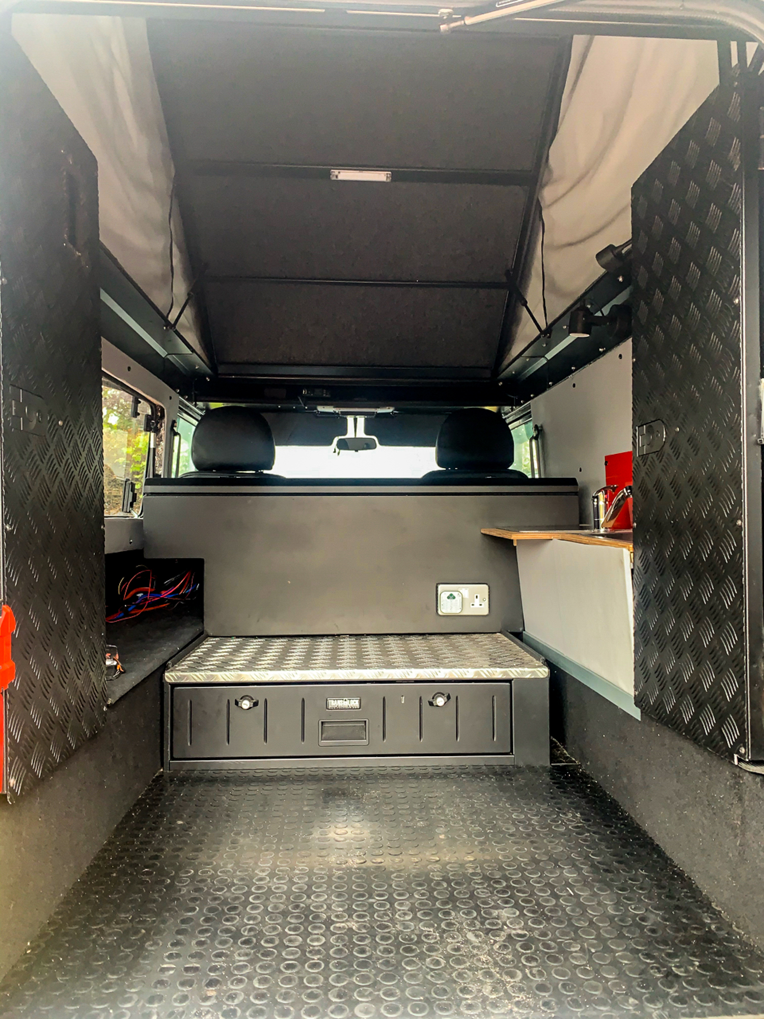
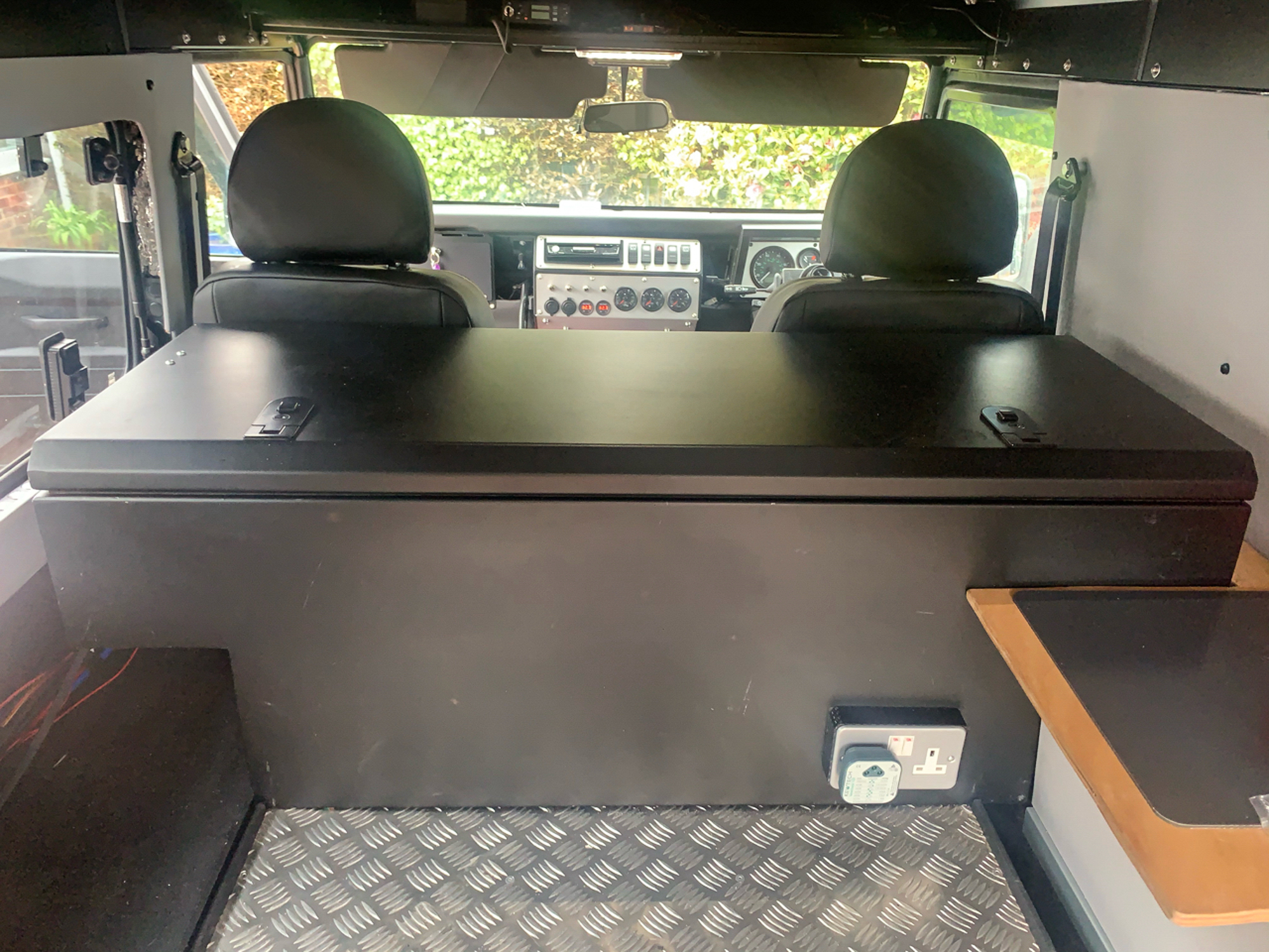
So we ended up with this layout.
The gun drawer was pushed right back up against the bulkhead and the steel cabinet was placed on top of it. Not ideal, but the space under the left and right hand sides of the back steel cabinet can still be used. I could have had the shape of the black cabinet changed, but I did not, in case I changed my mind on the layout.
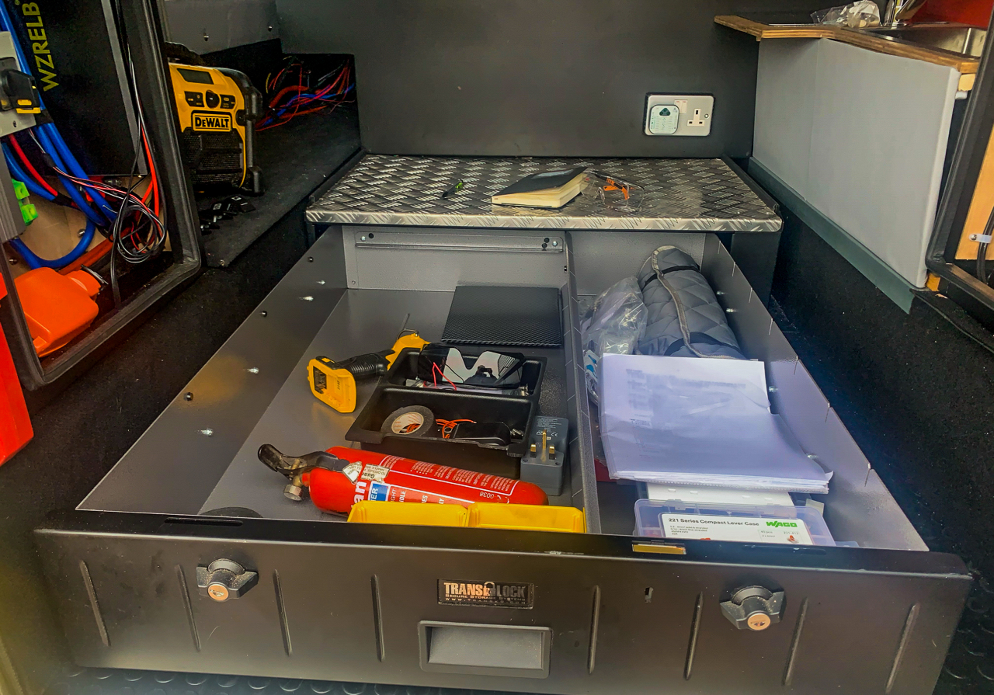
You can see how the drawer pulls out to give a fair amount of secure storage.
The leisure batteries will live in the black steel cabinet, which is why you can see all of the wires heading that way.
I bolted the “T” chest to the bulkhead through the back and to the gun chest though the bottom. I will bolt the gun drawer to the body of the vehicle through the floor, next time I am underneath with the drill! – Which will be when I fit the waste water tank which will be in the same area. I just did not want the fittings for the gun drawer to be under the water tank, in case of future maintenance.
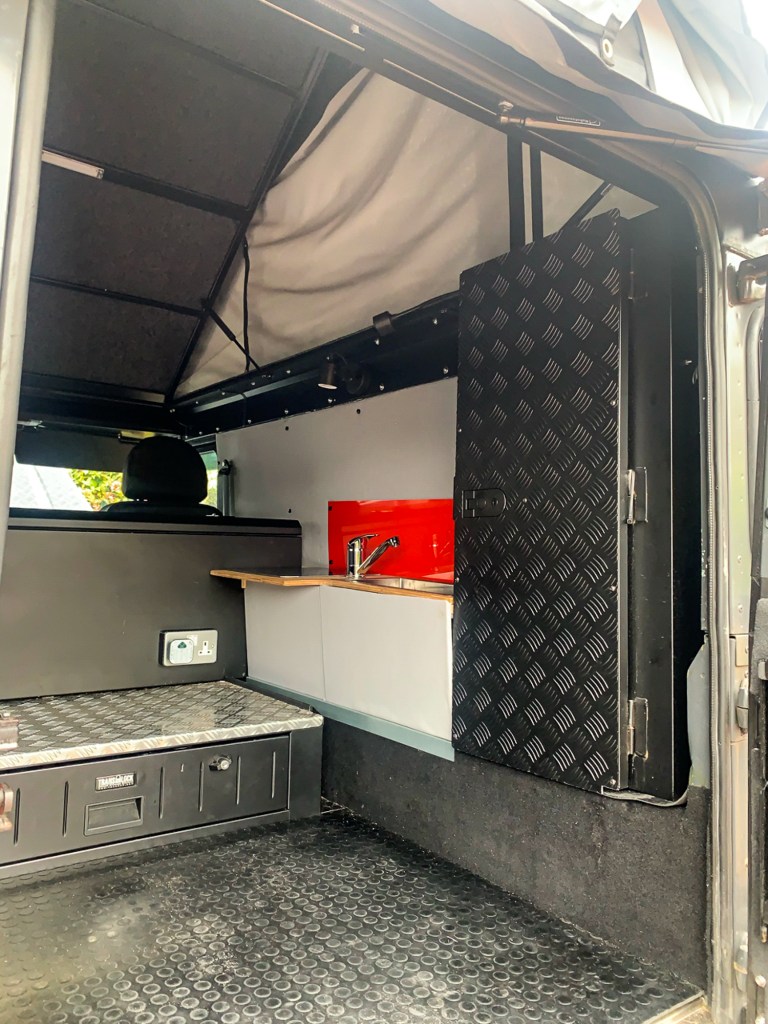
In the image below, you can just make out the other cabinets which sit just inside of the rear door.
Here is the cabinet on the drivers side which will house the water pump etc, there will be one on the passenger side which will house the electrics.
The problem that I mentioned earlier with the cabinets that sit inside the rear door, you can see one here with the black chequer plate, is that they are designed to lay flat with lid opening upwards.
We wanted to use them upright, but with the door opening towards the back door to give space inside if they were opened, this meant that the door would slide off of the pins in the hinge after a while. After a little puzzling and dismissing re-welding the hinges, a simple solution was figured out.
Each door has three hinges with a pin that can be removed. I fitted the door using the hinges on the top and the bottom, and replaced the middle one with a cable tie; that will prevent gravity from working when the doors are open, which will not be that often.
I hope all of that makes sense, please ignore the sink……….I will cover that later.
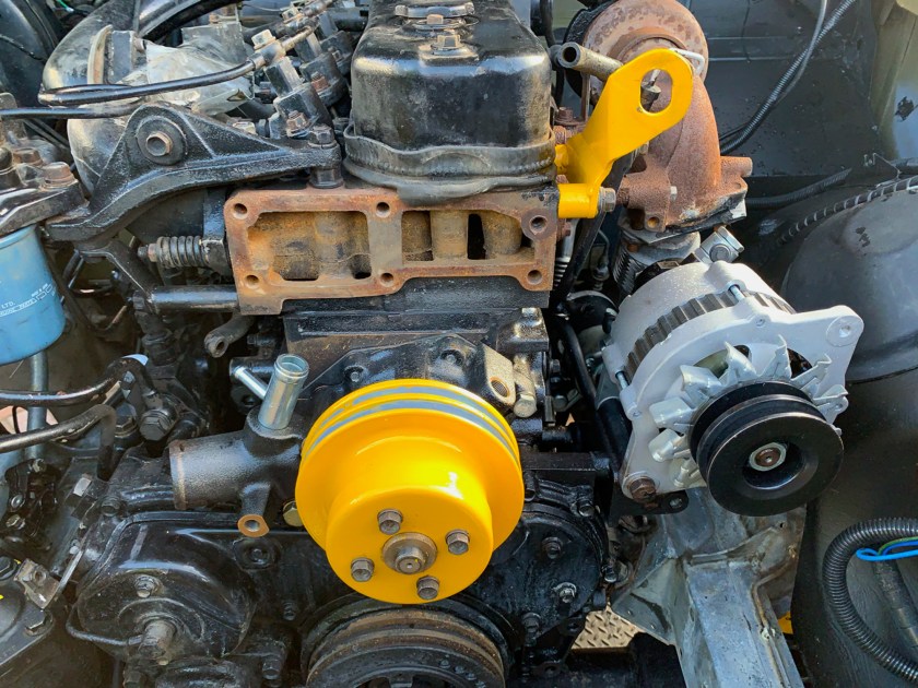
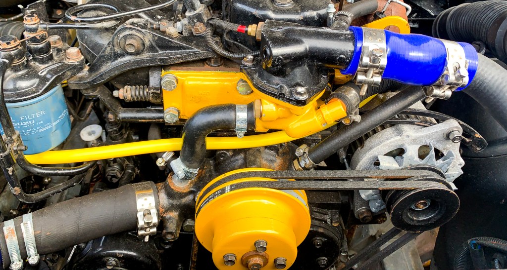
So, we left off at the point where the following parts had all been replaced/refurbished at the same time:
Heater fan and box Starter Motor Alternator Radiator Cooling changed to Electric Fan from viscous coupling Thermostat Water Pump and all of the nuts, bolts hoses, gaskets etc etc.
So it fired up OK and I could see no leaks………which was good. As stated in the previous post it was getting late, and it was not getting up to a temperature sufficient to start the fan.
So the next day we go out for a drive, not venturing too far from home. Eventually the water temperature gauge gets to normal; after staying static for ages, it made a sudden sprint for the middle part of the gauge – which was also a new part.
I could not hear the fan kick in, but the windows were open and there was no floor as I was still working on the interior, so it was somewhat noisy! I headed back to home to have a listen and to top up the coolant if required. Expecting a quick pit stop at home, I just pulled onto to front of the drive, not all of the way to my usual spot. The fan was running which was good, so I waited for it to stop and checked the coolant level which was also OK.
I thought then I would go for another longer drive………..but it would not start. The starter was operating, sounding like a machine gun, but was not engaging to turn the engine over. Luckily my friend Darren was passing by and he dropped in to do some trouble shooting.
We did all the usual checks, the hammer whilst cranking (not sure why this would work as it was a new starter), relays (these were all new), and checking that current was getting to the starter.
What, no current to the starter with all new wiring? The battery isolator had failed. Once bypassed it still did not start – a red herring, but something thats needs to be dealt with (See another post)
We did notice that the earth between the block and the chassis was getting hot, very hot in fact and smoking…………This is ironic as it was the only piece of wiring that I did not replace. I did take it off and clean it up, but because it seemed to be copper I took the executive decision to leave it on. That will teach me.
We decided that the earth was probably the problem, so the next day I made up a replacement – no smoke , but no start either. The Perentie was blocking access to the drive, by chance I had moved Benita’s car onto the road in order to get the Perentie out of the drive; which was lucky for me!
I had to get it moved, so I re-fitted the old starter and – it fired up on the button
Oh, what to do – could it be the new starter; which I had had on the shelf for over a year – out of warranty………..
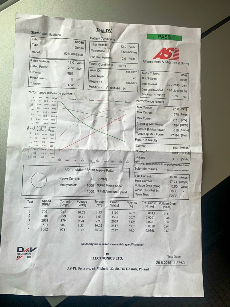
Anyway I called up the supplier, the Alternator and Starter Motor company, who were extremely helpful. They walked me thought a few tests during which it “machine gunned” again and they agreed to send me out a replacement.
Replacement Unit and test report.
Once the replacement was fitted……………same problem, no start, which made me sad!……..I hasten to add that it was easy to fit the Starter when everything was stripped off of the engine whilst doing the other work, not so simple now. It is heavy and awkward to manoeuvre into place, especially when you are on your back in the cold.
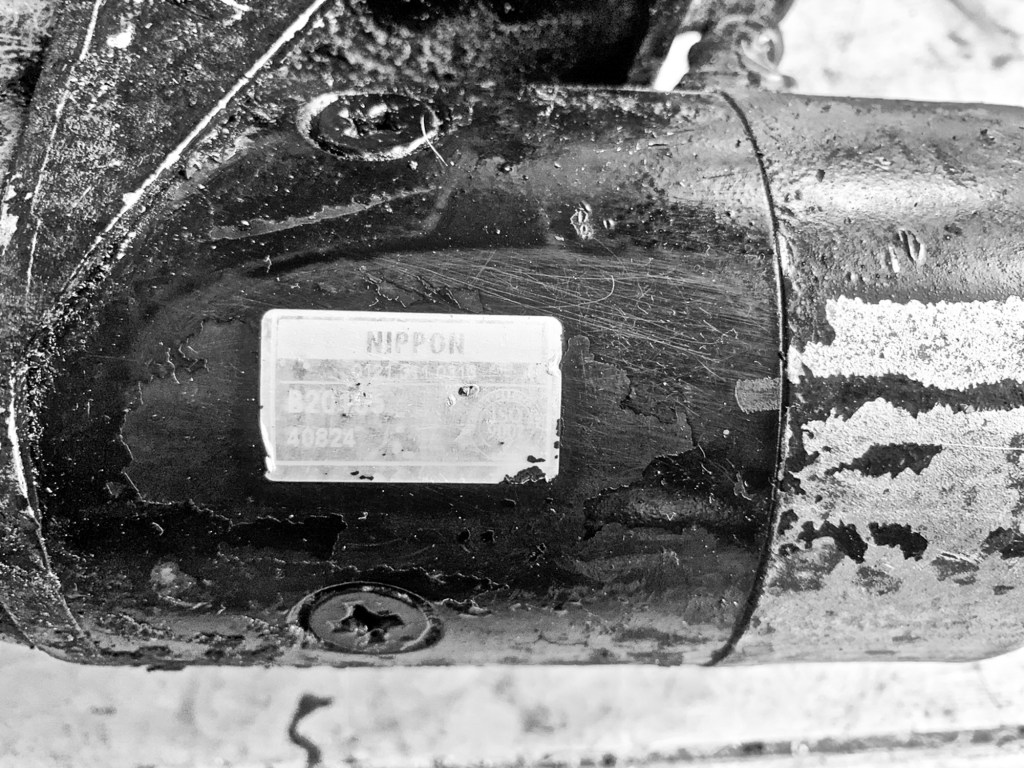
Now these starter motors are not the easiest to find and I found the part number by trawling a few forums, as I could see no part number on the original whilst it was on the vehicle. So in desperation I started to hack the gunge and paint off of the original, eventually I came across as sticker which was almost illegible, but I could make out a telephone number. A quick google brought up a supplier of Starter Motors in Birmingham……………..Nippon Distribution – makes sense for an Isuzu part.
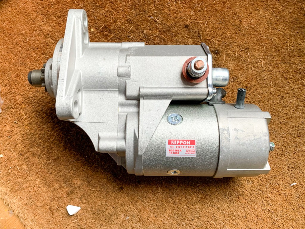
Replacement from Nippon Distribution and the information on the old unit.
A quick phone call and a new unit was on the way to me. My original unit was suppled by these guys many years ago, the serial number which I could just read on the sticker was some 18,000 units behind where they are now, so an old unit.
Anyway, the new unit was fitted (getting good at that now) and the Perentie started – no problem. No idea what the issue was with the other starters – they were not original parts, which are impossible to get, but made in Poland. The Starter motor and Alternator Company took the replacement unit back and refunded me – so a credit to them.
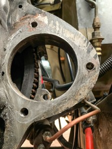
Starter Mounting point on the Bell Housing
i did notice during all of this that the Bell Housing (which was not the original) was open at the rear, exposing the Starter to the elements. A job for the future is to make up a plate to protect it.
So on with replacing the Brake and Master Cylinders……..
As I have said before on the blog, most parts from the engine towards the rear of the vehicle are Land Rover, but engine based parts are either Isuzu or available from Land Rover Australia only. A search for these takes you to either Landybitz or KLR in Australia.
My friend and Perentie “partner in crime” Darren was having a box shipped from KLR Australia, in which there was some room……….
So, I ordered up a Water Pump, Thermostat and gaskets, and a few other bits that I may need in the future. There was still room in the box, so I added a rear disc brake conversion kit for the rear axle – more of that in another post.
From inception to arrival this took months, mainly down to KLR being useless administratively. Once the box was shipped, it arrived in just a few days.
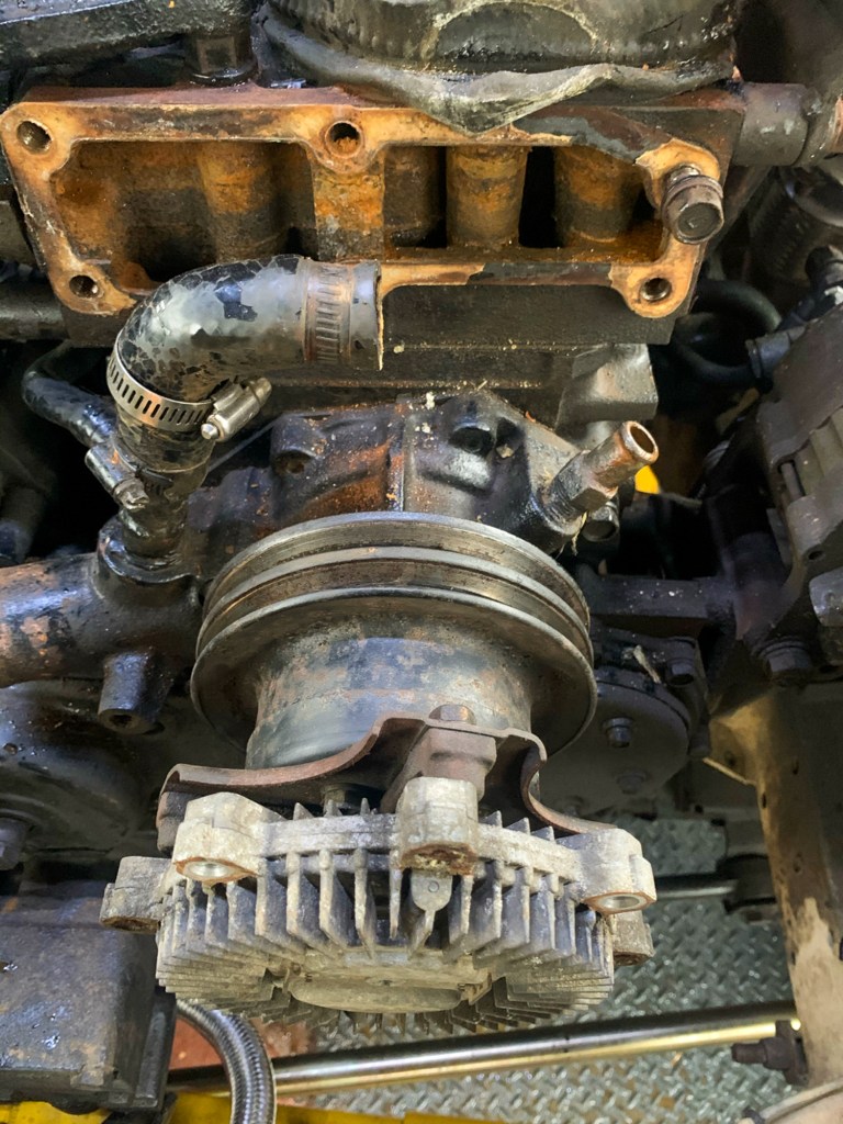
So now it was time to tackle the job that I had been planning for nearly year!
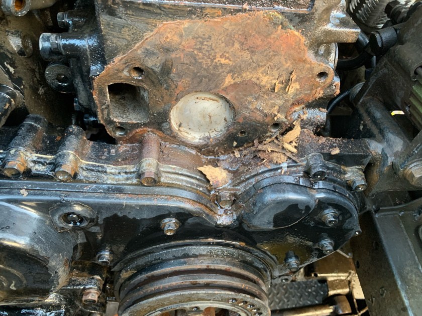
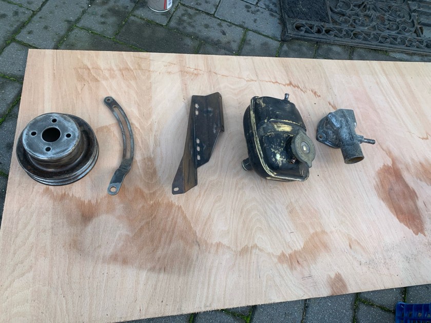
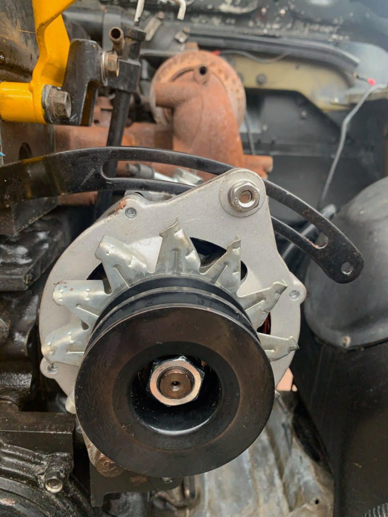
I removed the bull bar and the front panel in front of the radiator for improved access and then the radiator, viscous coupling, water pump, thermostat and the housings for the thermostat and water pump. With everything stripped back, I also removed the alternator and starter motor, replacements for which I already had. All of the water pipes came off as well as they were all past their best.
The heater box came out as well as it was in a very sorry and rusty state.
So long story short, all of the old parts and the heater box casing were stripped back and repainted. A new matrix was purchased for the heater along with bulkhead seals. I am not sure that this will make much difference as the heater on the Land Rover is archaic to be polite! But a least it reduce the possibility of a future leak as access to it is a pain…
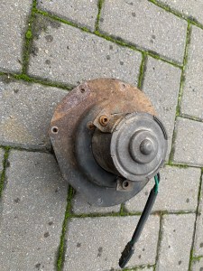
Rusty heater box and fan, which did still work!
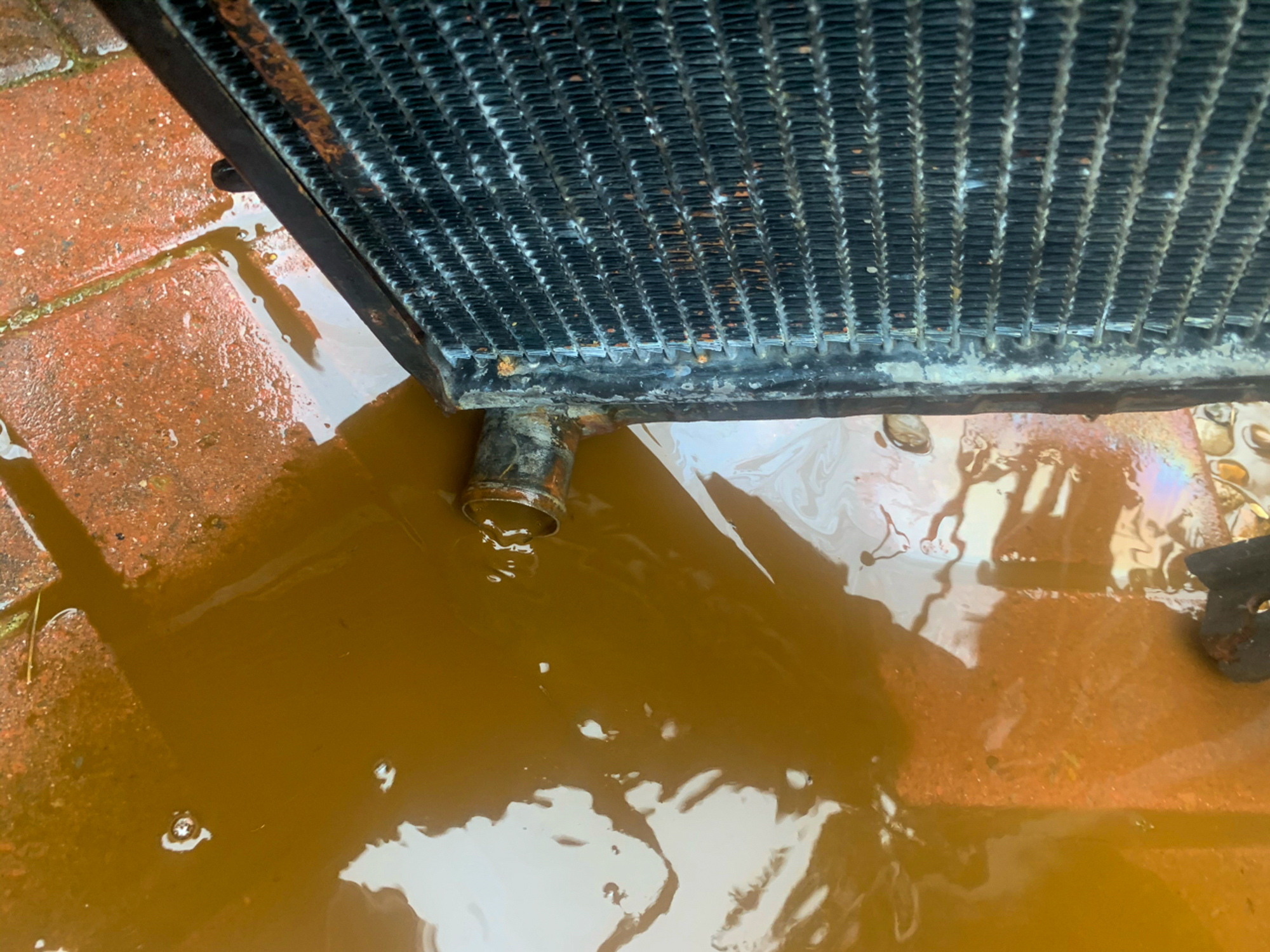
Flushing the old rad – gunge, but not too bad.
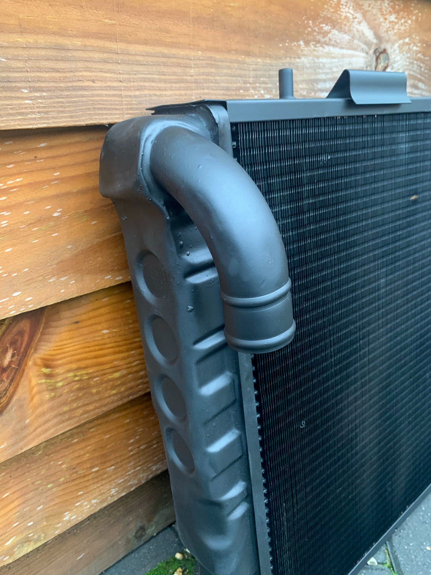
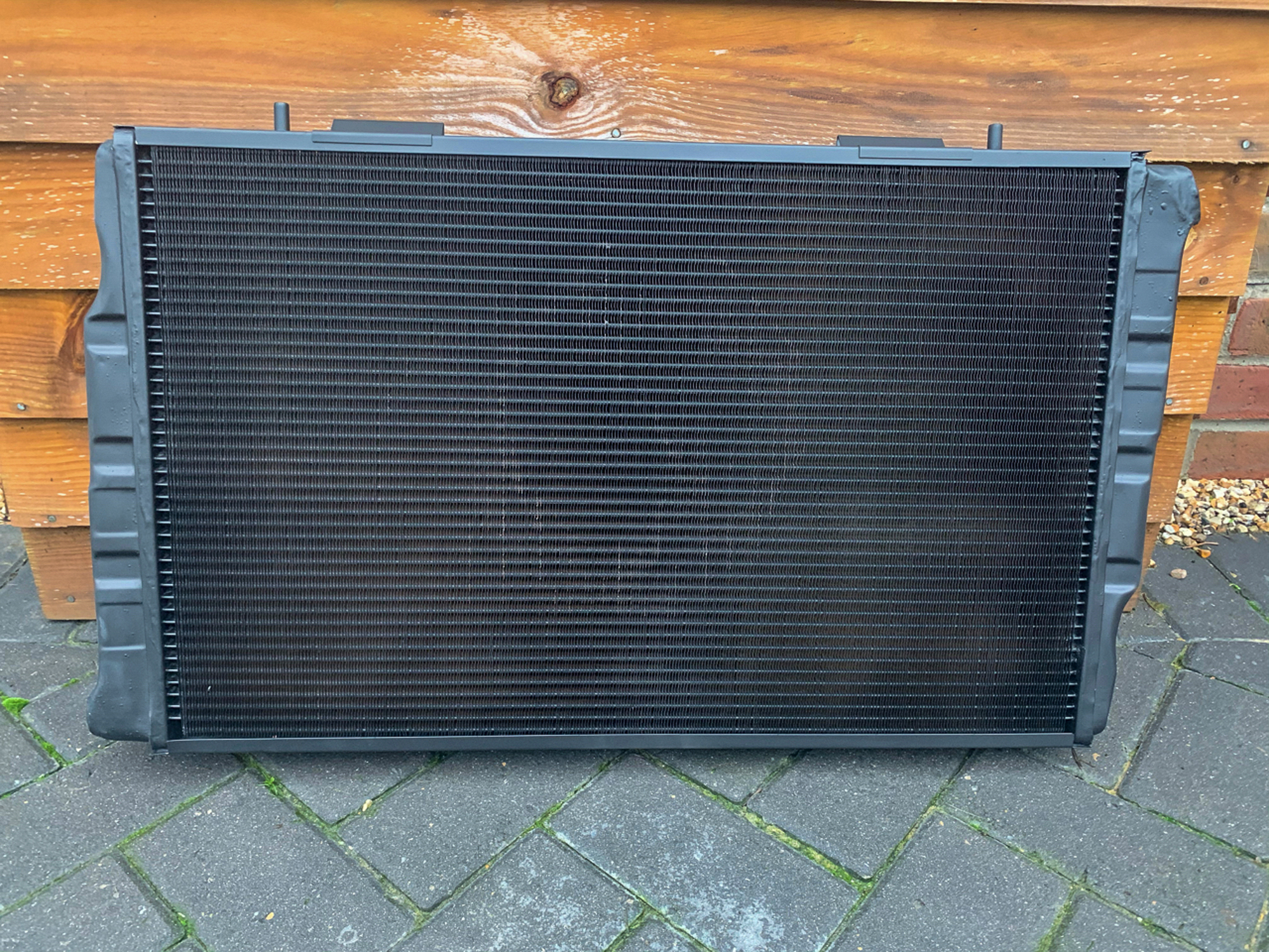
The radiator went off for a re-core with a more modern efficient core with Paul Slack ,who provided an excellent and efficient service. This is his e-mail – paulslack55@btinternet.com.
The Radiator was as I thought from a Land Rover V8, but with the inlet and outlets switched around.
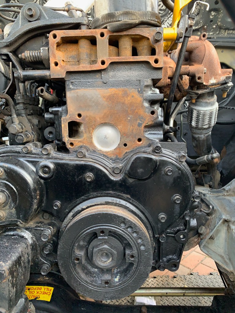
Everything went back together without “drama”; believe it or not…………..
The only delay was that I wanted to replace the corroded bolts that held in the Water Pump and Thermostat housings, together with the barbs that the heater hoses attached to. It turned out these the threads were a fine thread metric and my usual supplier did not stock them. Again, e-bay to the rescue……….
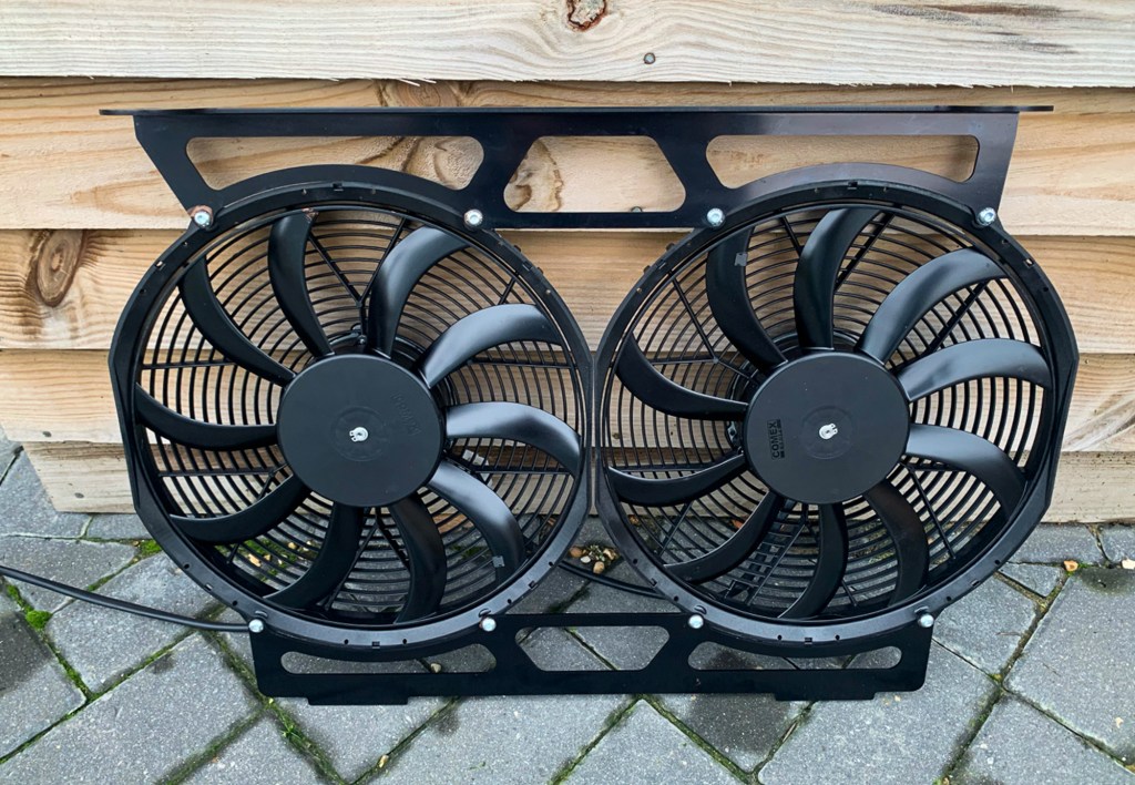
The viscous fan was not re-installed though, this was replaced by a Revotec Electric fan which I have mentioned previously; the wiring for which was already in place.
New Revotec Fan.
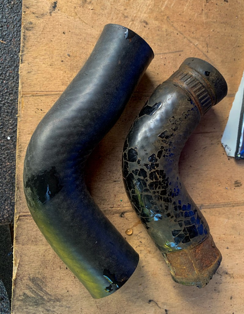
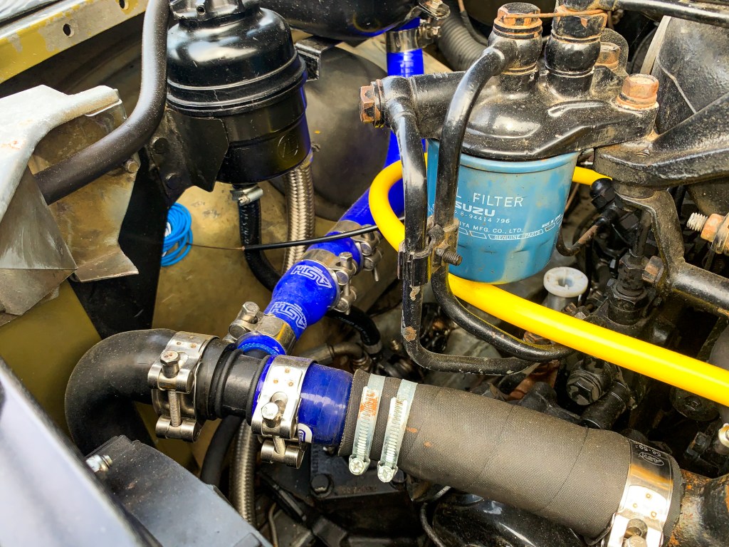
Replacing the hoses was more of a challenge than I expected though, as nothing was standard Land Rover. I measured everything up carefully and ordered what I needed in silicon. This included water and oil pipes that go to the alternator for cooling and lubrication.
Some of these pipes fitted not problem although the ones for the alternator were tricky to fit because of the room that was available.
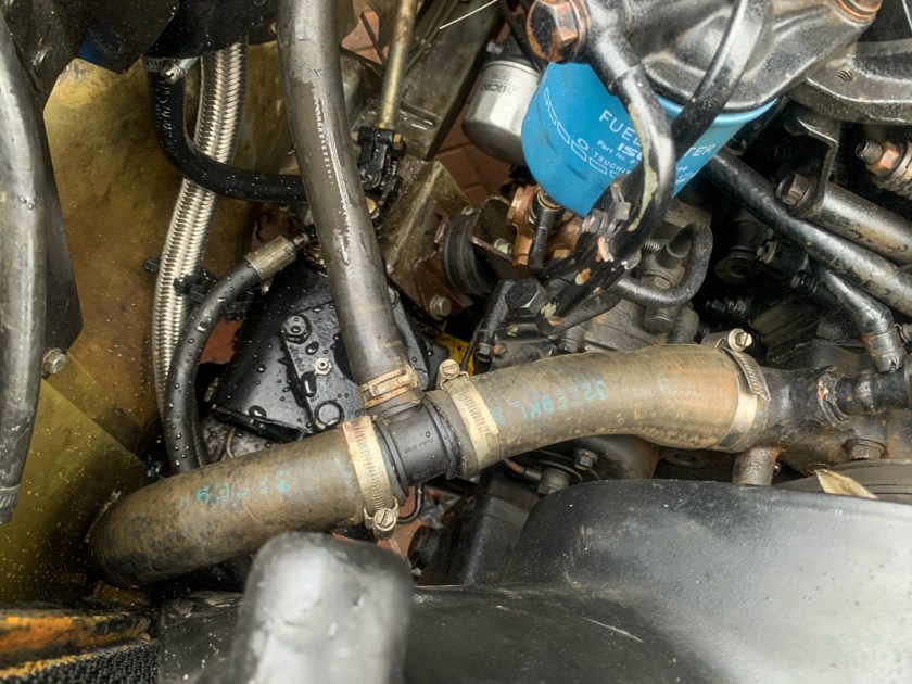
The main problem was the top and bottom radiator hoses. The top on right had to be cut to fit the sensor for the electric fan which made the length of the hose very short. Because of the bend, the silicon (which is less flexible than I thought) was under tension and just would not stay in position. A similar situation for the bottom hose on the left, which has a “T” so coolant can go up to the expansion tank, so that the coolant level can be checked easily.
Its did not help that the ends of these hoses had different internal diameters which necessitated a reducing piece.
Eventually after trying many different options I abandoned silicon (for the tricky bends) and took myself over to Paul Light Land Rover in Hordle (again!) with the original hoses which had the correct bends.
Paul, who is forever helpful, went through his stock and eventually found some hoses that had similar bends to the that I needed. I cut these down and eventually ended up with a complete cooling system.
In retrospect, I could have ordered these from Australia where they are available. but at the time I wanted to go silicon – the best laid plans.
I refilled the system with coolant and fired up the engine to check for leaks and to see if the new fan kicked in at the right time. The vehicle ticked over on the drive with no leaks which was a result. It was not getting hot enough though for the fan to kick in in. It was getting late, so I decide to wait until the next day to take the car for a drive to get the temperature up to. proper working level.
I did not know at the time, but that was the beginning of another challenge
I have mentioned these before, purchased from Land Rover Defender Security, also the fact that we are trying to make the vehicle as secure as we can during the build.
The security hinges, covered previously, and the dead locks fall into the category of “visual deterrent”……move on, find something easier to steal is the message.
The locks, one for each front door and one for the rear, come with common keys and a set of very blurred instructions, which, are not clear; nothing new then! One page even tells you what to do, with pictures and then tells you not to do what is shown as the measurements are incorrect.
So, this falls into the list of Land Rover jobs entitled “This is going to be a pain”, rather than the list entitled “relatively straightforward” that then turns out to be a pain. This why the locks have been sitting on the shelf for a few months.
Anyway, the day has come, work has started on the interior and the rear door needs to be stripped down as there is some corrosion around the seams; so a good time to do the locks. Luckily, the back door is far from a basket case, and some rust removal, primer and paint, will keep it in service for a few more years. The rear wheel carrier needs to be unbolted and the fitting plate for this also needs rust-proofing and a re-paint.
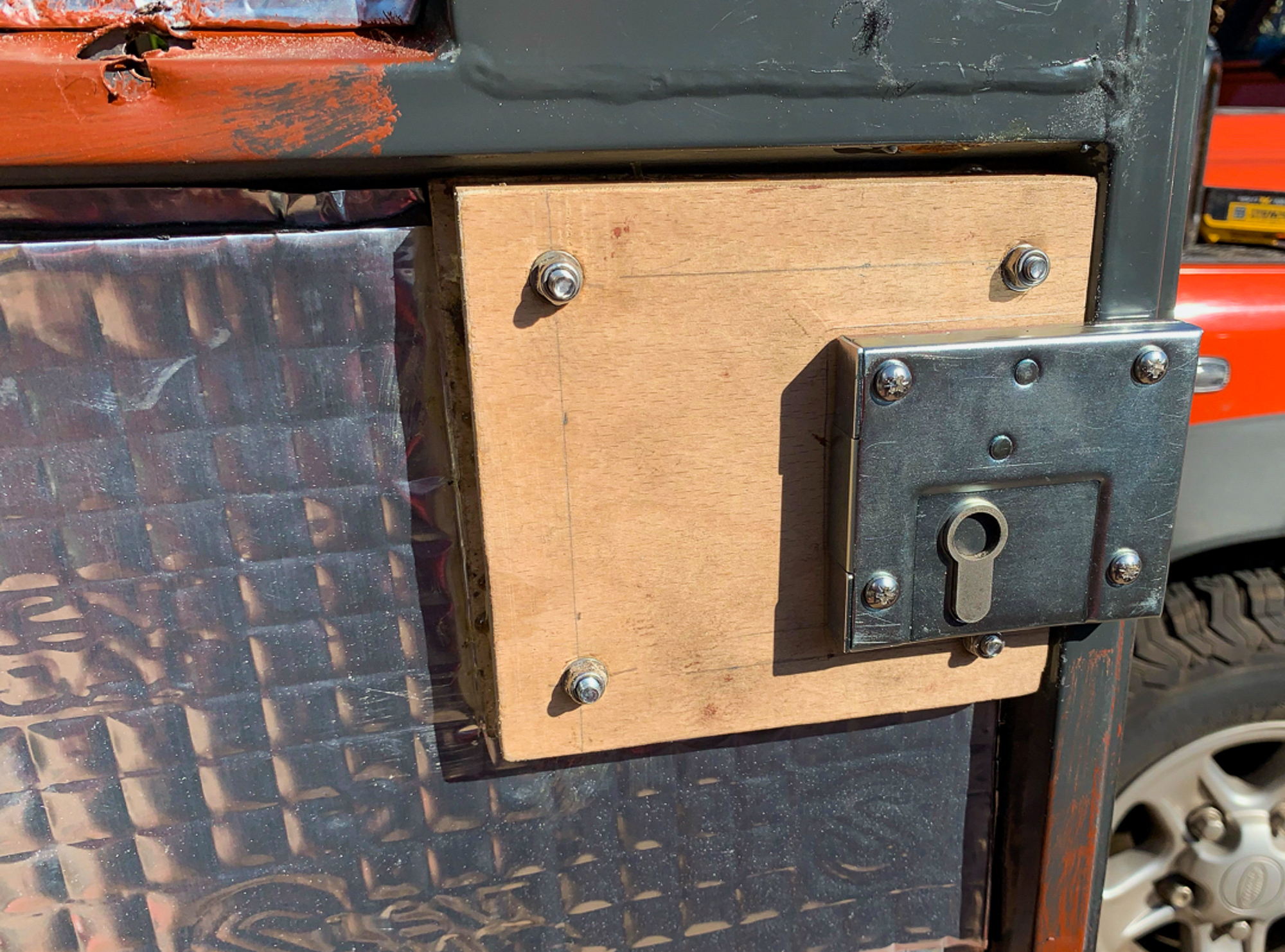
So onto the fitting the rear lock.
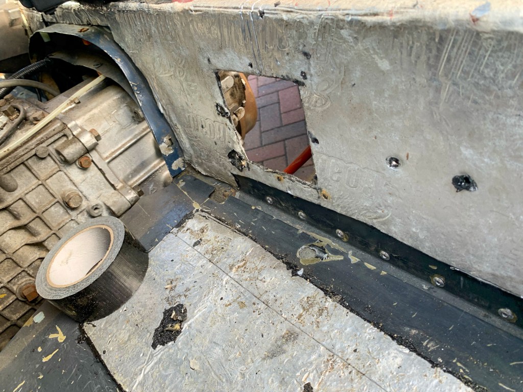
There is nowhere to mount it on my door! – The lock is clearly designed for the later 2007 on – Puma models which have a plate under the standard lock, onto which the dead lock can be mounted. So I bonded a couple of pieces of plywood together to get the correct thickness and fitted this to the door, to give me a mounting point.
I took the opportunity to add some sound proofing to the rear door and to change the standard lock, that was starting to jam.
I also moved the position of the lock down a little from the suggested placing. This moves the key position on the outside of the door down, so I would still be able to use the lock when fitting a slightly larger spare wheel – more forward thinking!
Rear lock position
The lock keep was straightforward to fit, so onwards to the front locks.
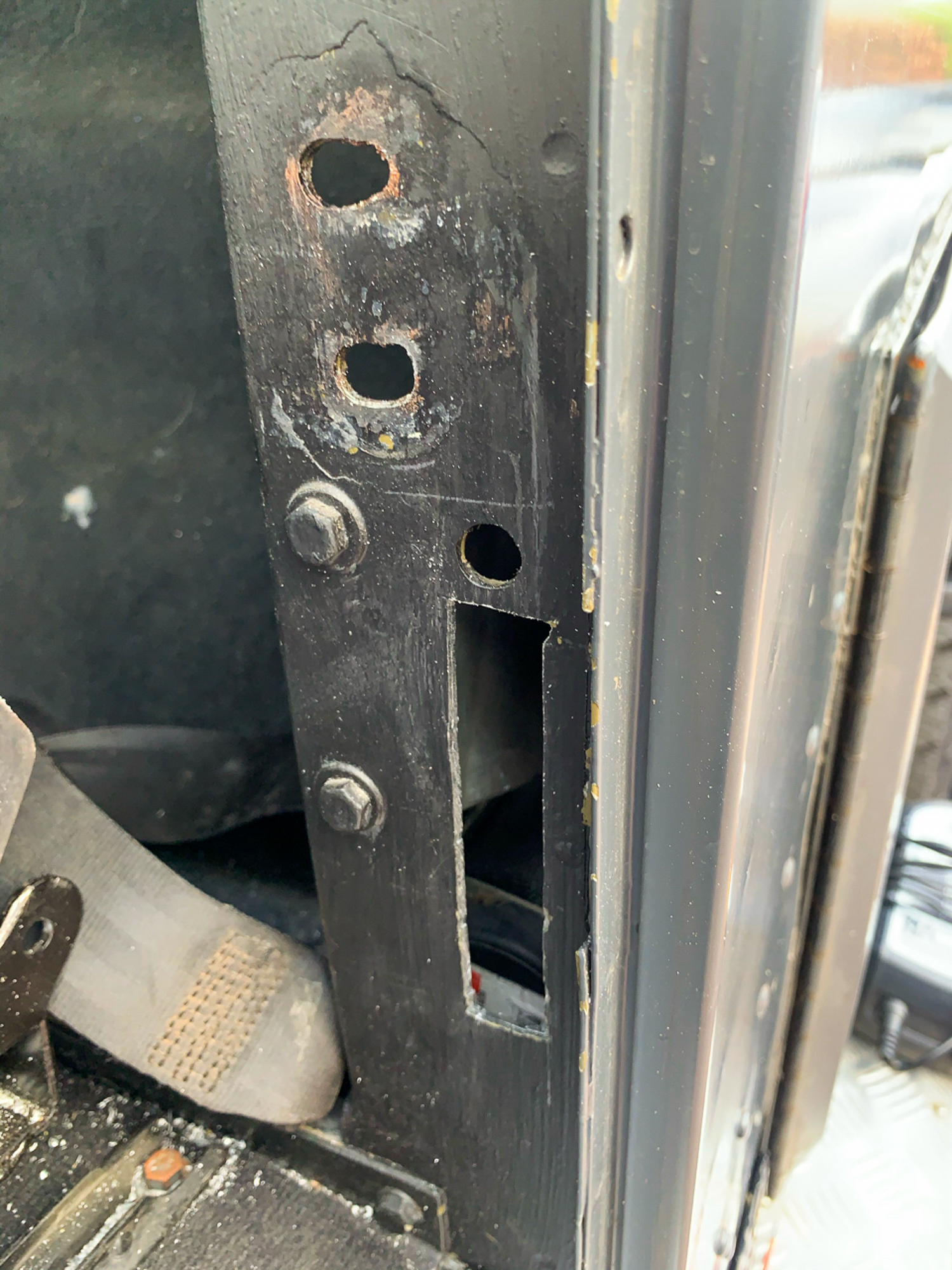
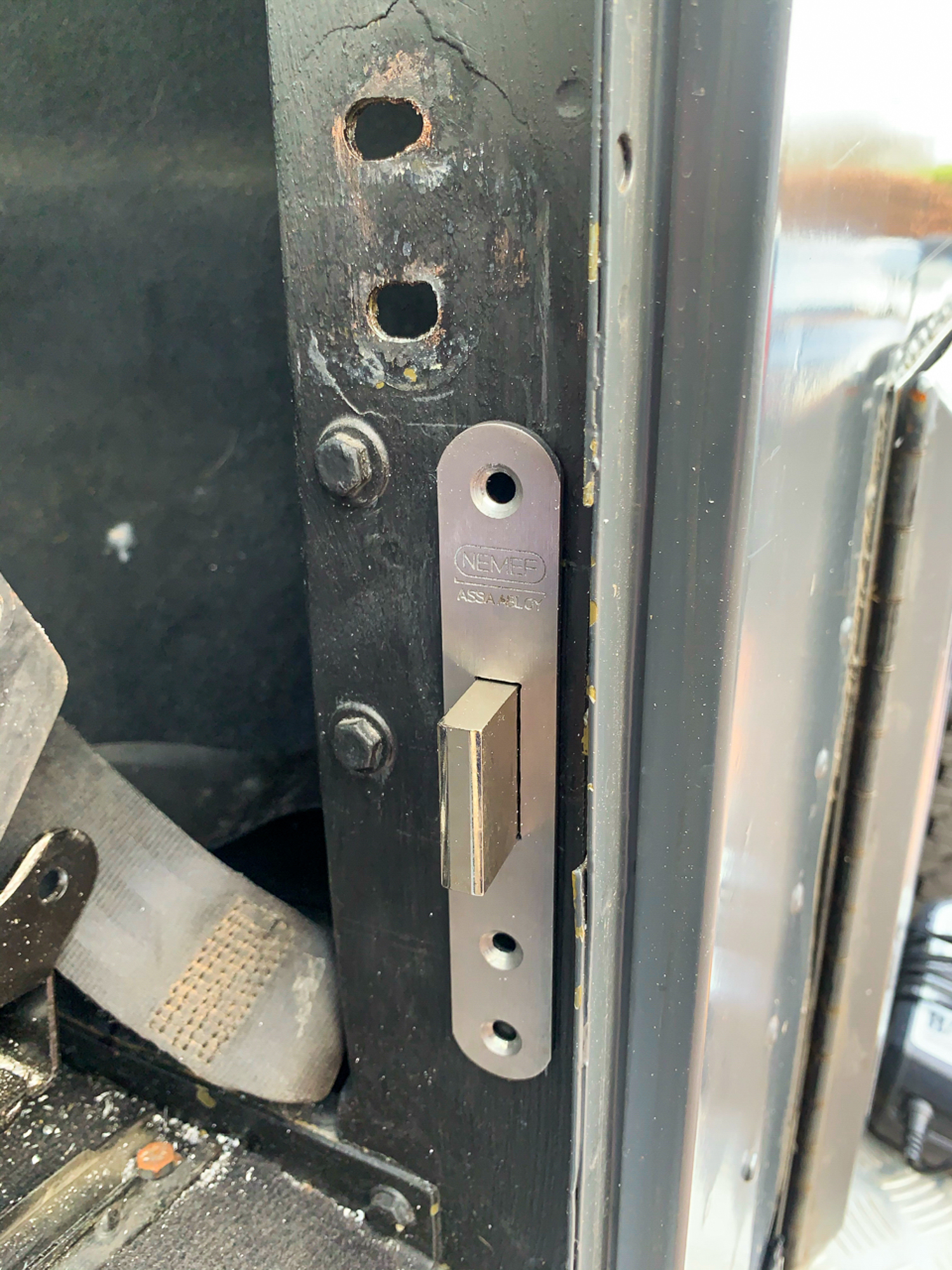
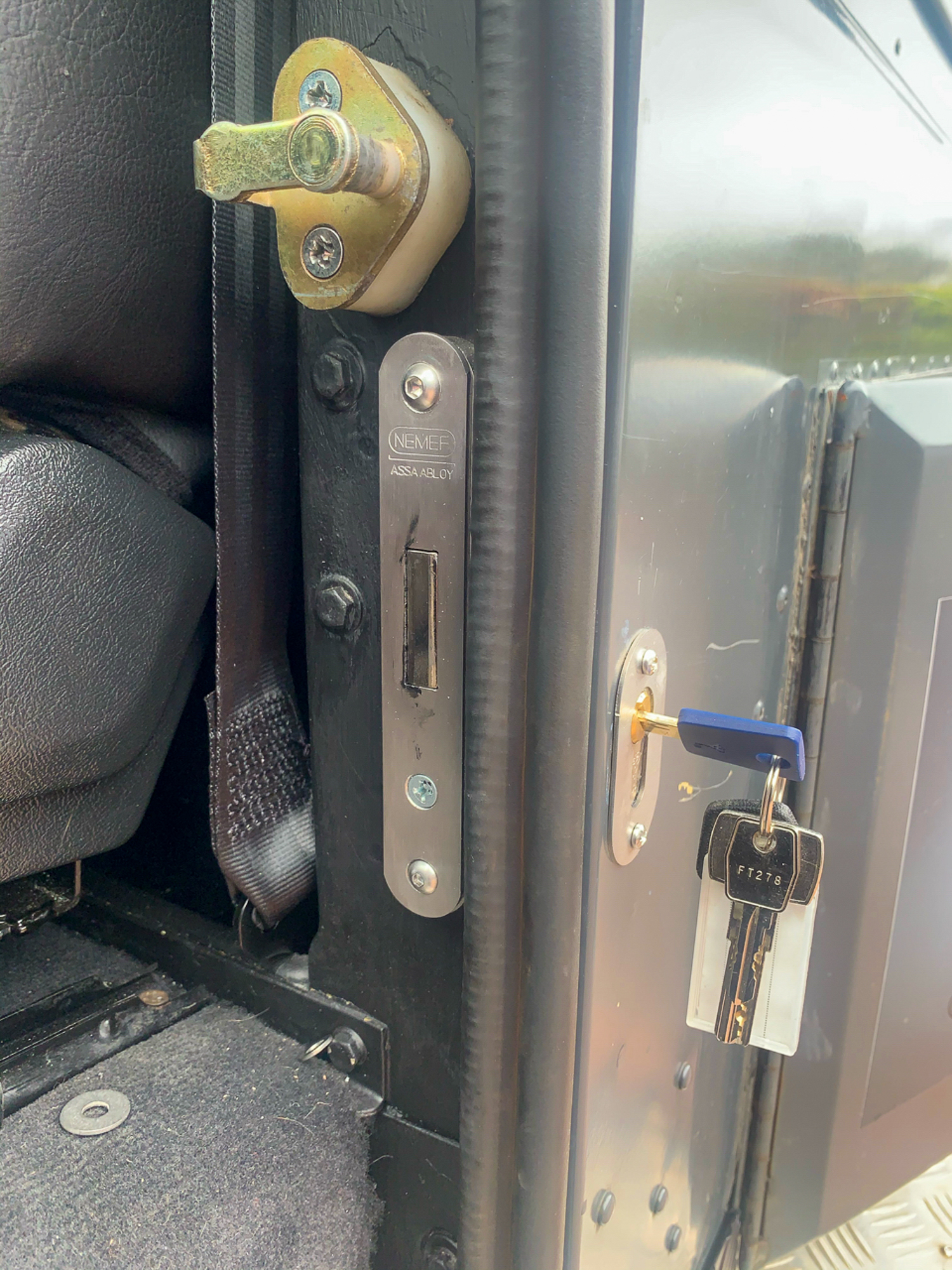
These were tricky as there was little room for error, I decided to ignore the measurements in the instructions and work them out for myself. The lock itself fits into the door post and not only has to avoid the existing door shut catch, but the seatbelt mounting, which sits behind the seat inside the door (B) post.
After some careful measuring and judicious drilling, not to mention the “getting the correct size” with the file, the lock eventually was bolted into place. I removed the door shut, to make access easier, hence the two holes above the lock.
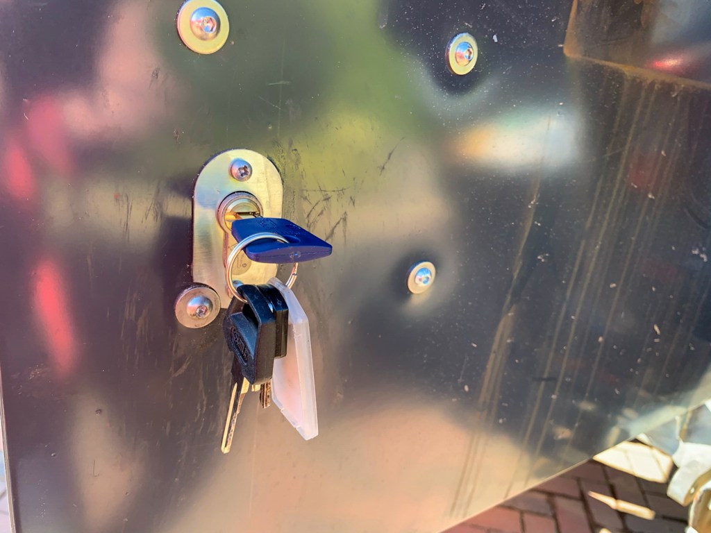
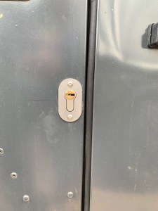
Then, I had to figure out where in the side of the car I needed to drill the hole for the key to fit. I used the measurements given as a guide and managed to get a pilot hole in roughly the right place. It was, as they say “a right game” to enlarge the hole to get the key to engage on the lock and to turn, without making the hole so large as it would not be covered by the trim. Anyway, eventually this was achieved; the word “eventually” apparently, means a very long time………
Lock cover fitted just behind the front door.
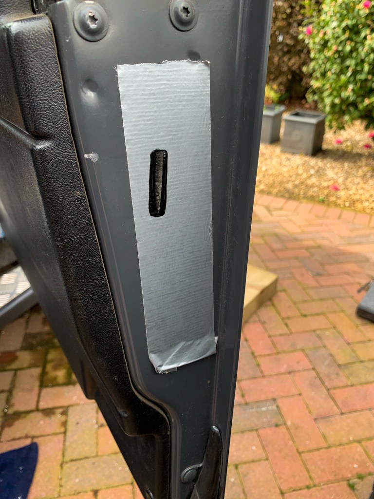
So all I had to do now was fit the keep in the door, in the right place. An issue here was that I have Puma Doors on a 1989 body, so the where the lock throw goes through the keep is perilously close to where the standard door lock is fitted. I did think to start with that it would foul and not fit.
The puzzle was exactly where to drill the hole………….so I place a piece of masking tape on the door shut and put a large blob of paint on the lock, shut the door and operated the lock a few times – this gave me a pretty good idea of where to drill – not bang on, but near enough. Out with the file again!
Door lock keep template.
It was a painstaking task to get the hole and the keep fitted so the the throw would fit, but I got there in the end. A learn from the first door, was to tighten the actual lock in the door properly first; I got it all to fit and then tightened up the lock and then had to tweak the keep as the position had changed. I suspect that this might be an ongoing issue when the door moves with use – we will see.
Overall, a good job done and very pleased with the result and the product, although a decent set of instructions would have been helpful.
We all know that Defenders are not exactly secure and we are gradually adding security features into the build. A previous post cover the fitting of alloy door and bonnet hinges with security bolts as a visual deterrent.
The Perentie had a standard battery isolator fitter on the passenger seat box just behind where your legs would be; this just had a regular red plastic key. I ordered one that had an actual key from Land Rover Defender Security.
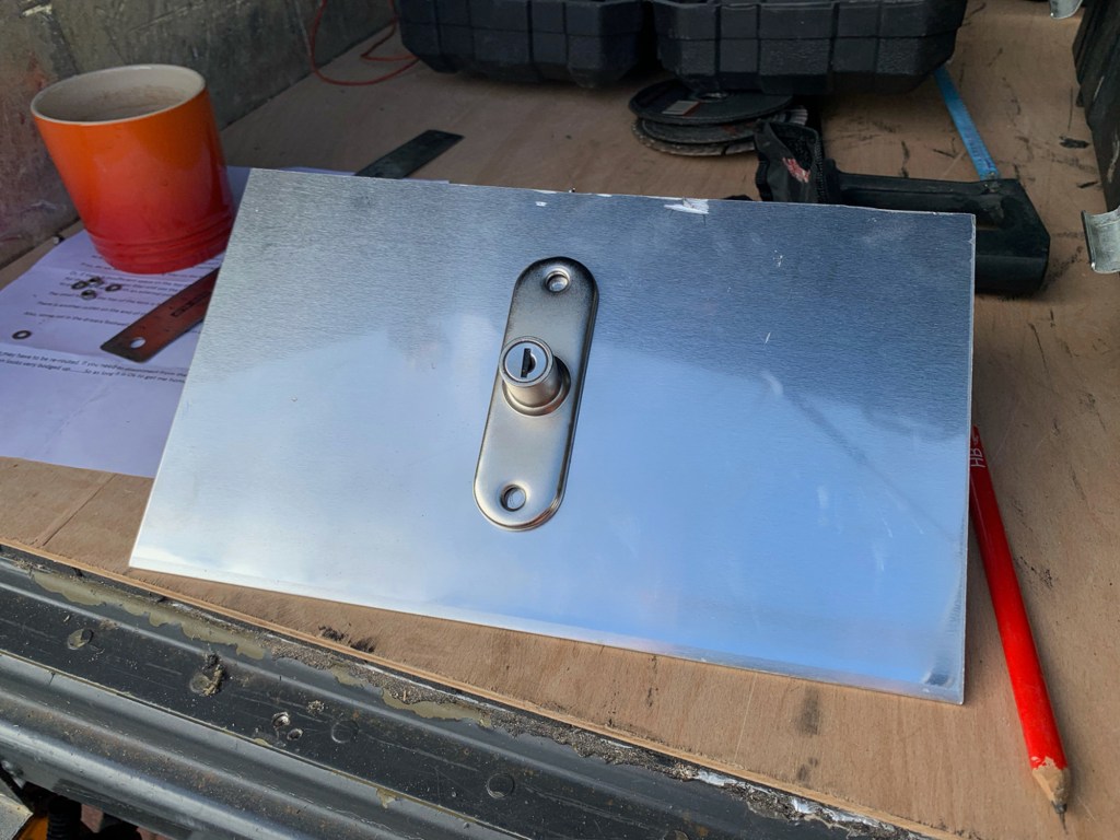
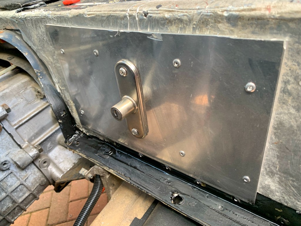
Removing the old isolator left a huge hole in the seat box. So I made up an aluminium plate and mounted the new switch in that.
When I moved the battery, I had left sufficient slack in the main cable to allow me to cut and link the main starter cable into the isolator – sometimes forward thinking works…………
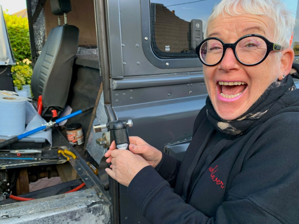
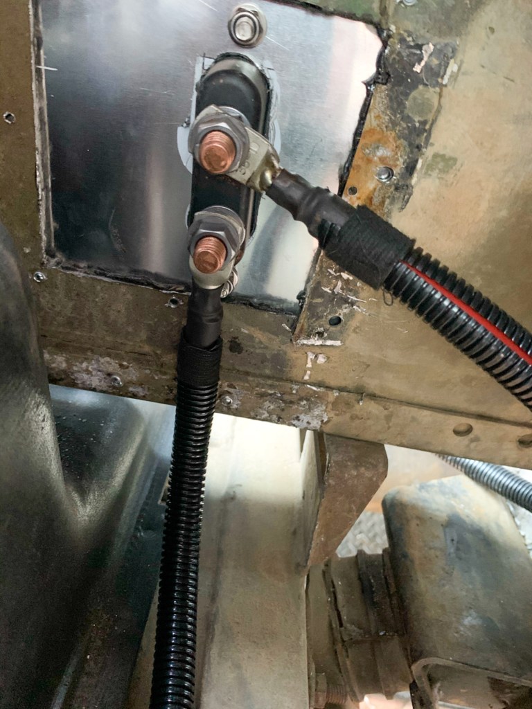
There was not loads of room to crimp the heavy battery cables, so I enlisted the help of Benita to hold the wires whilst I crimped – we added some solder to the joint, just to make sure! – Benita was in charge of the heat, we used her cooking blow torch.
Terminals crimped and connected.
The seat box was later trimmed with carpet; overall a neat job.
However, when the starter motor failed, which is covered in another post, we identified that the isolator had also failed. This became apparent when we were checking for current at the starter motor; one of the initial checks. We needed to bypass the isolator to continue fault finding.
Land Rover Defender Security did send me a replacement, which did sit on the shelf for a while before I got around to fitting it. It was a job that I did not really want to do as it involved removing the carpet that I had carefully laid.
Anyway, I did the job and then when testing the device realised that they had sent me keys that did not fit it! – I should have checked.
I did send them very polite e-mail asking for a solution and received no reply. I then called a couple of times only to be put through to voice mail – two calls, two messages – no response. I then sent both devices back “signed for” asking for a refund to date – no response. So I will not be ordering from them again.
I hope the door locks I bought from them are OK – more about that later………….
I got another identical unit from e-bay – £10 cheaper – works just fine.
A learn here is that the isolator cuts power to anything the is powered by the main starter battery, which includes the radio – which promptly forgets all of the settings the you have carefully programmed into the endless menus. So I will be running a supply to the radio from the leisure batteries once they are fitted.