This particular job has been in the planning stage for at least 18 months…………
Shortly after purchasing the Perentie I knew that I wanted to upgrade the rear drum brakes to discs. There was no conversion kit available in the UK and the only option would be to swap the whole axle, maybe from a Discovery 1. I wanted to retain my strong Salisbury axle, so this was not an option.
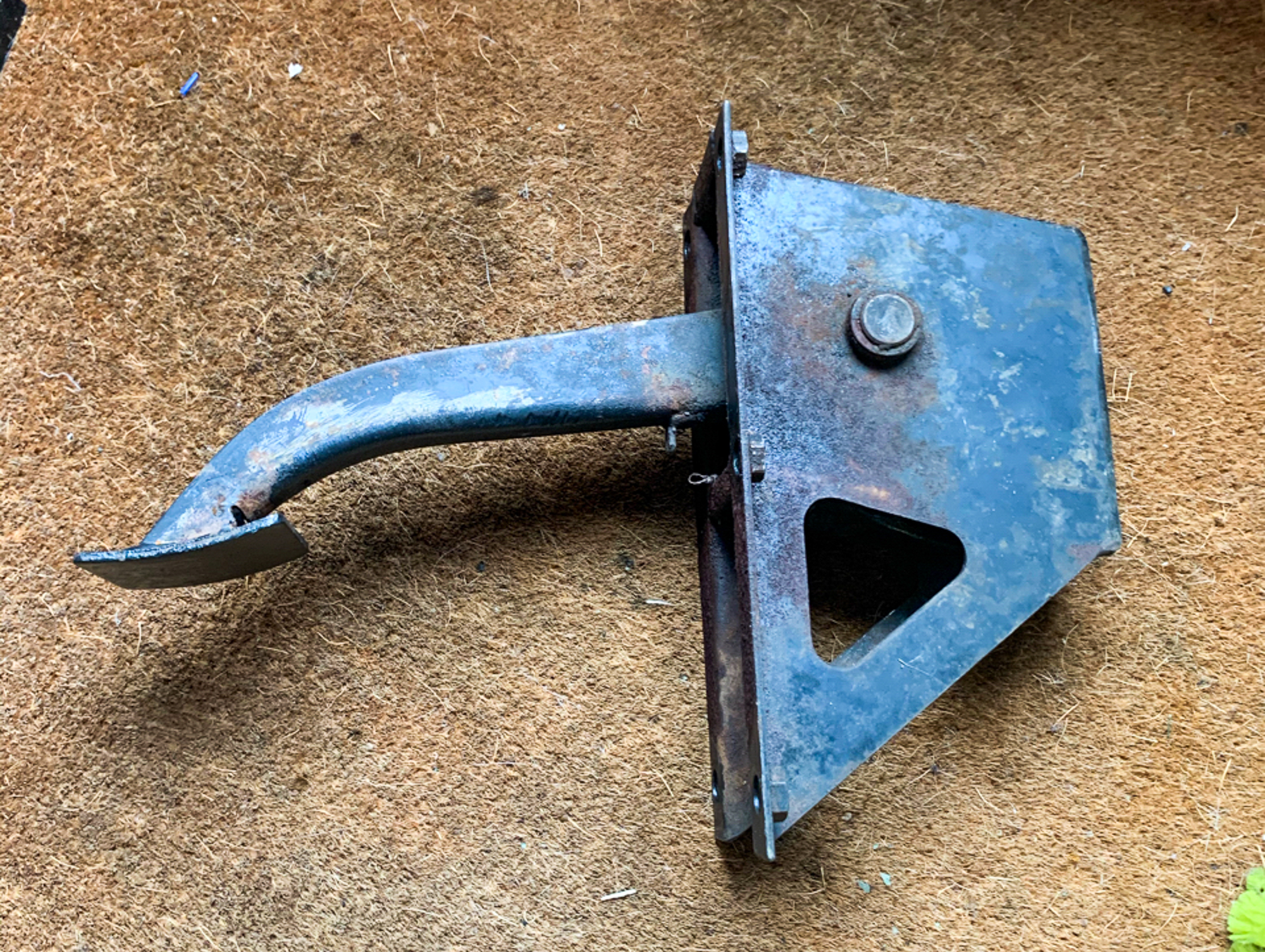
My friend and Land Rover afficianado Darren pointed me in the direction of KLR Land Rovers in Australia, the same outfit from which I was sourcing the Water Pump and related parts. KLR make a specially machined hub and bracket than enables the discs to be bolted on to the Salisbury rear axle. I had discs on the front already.
The parts were ordered up and have been sitting on the shelf since January 2021.
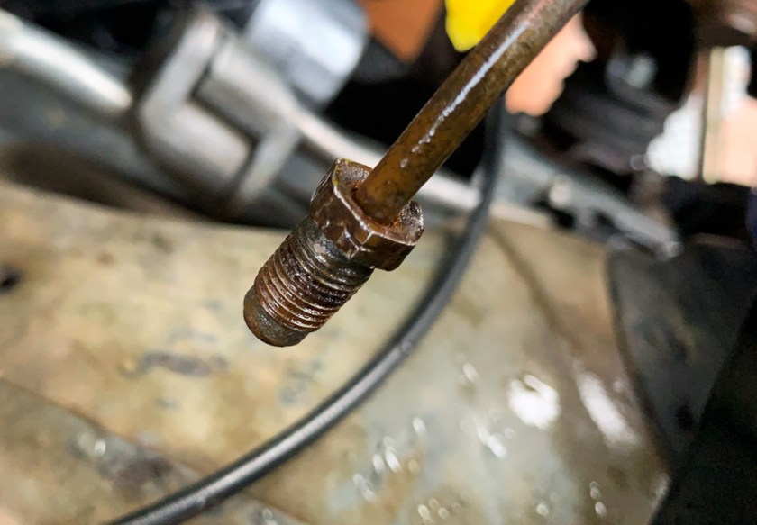
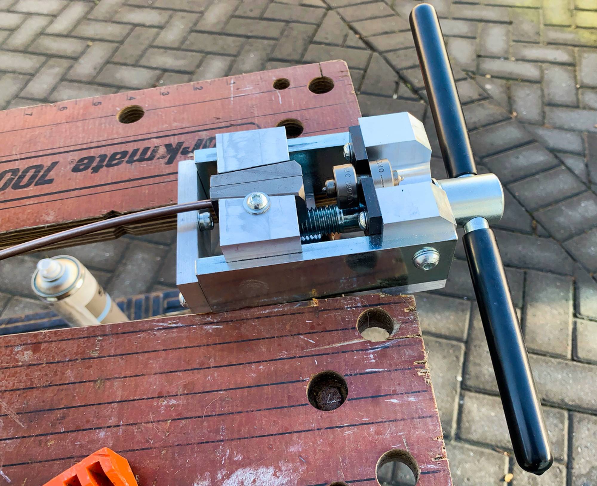
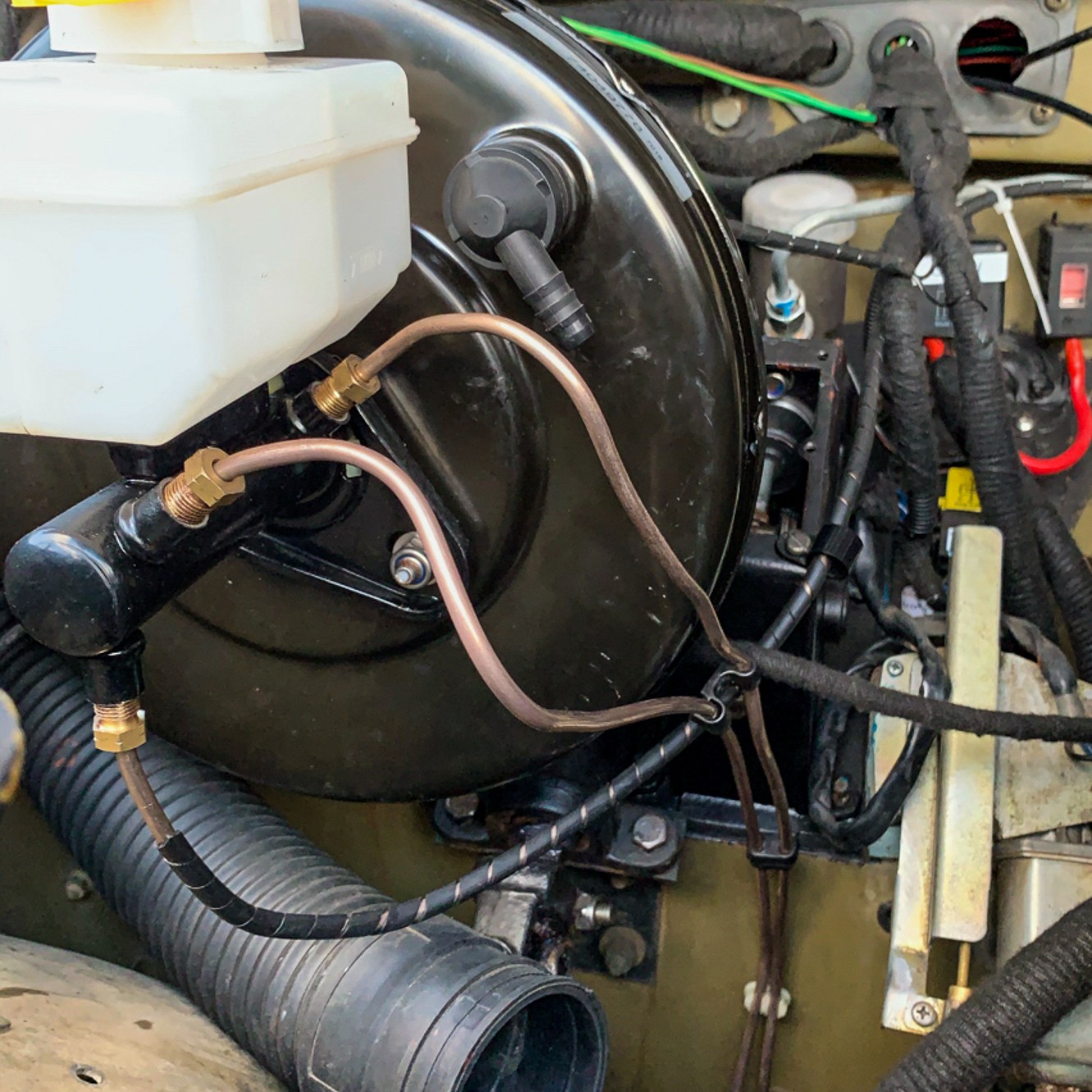
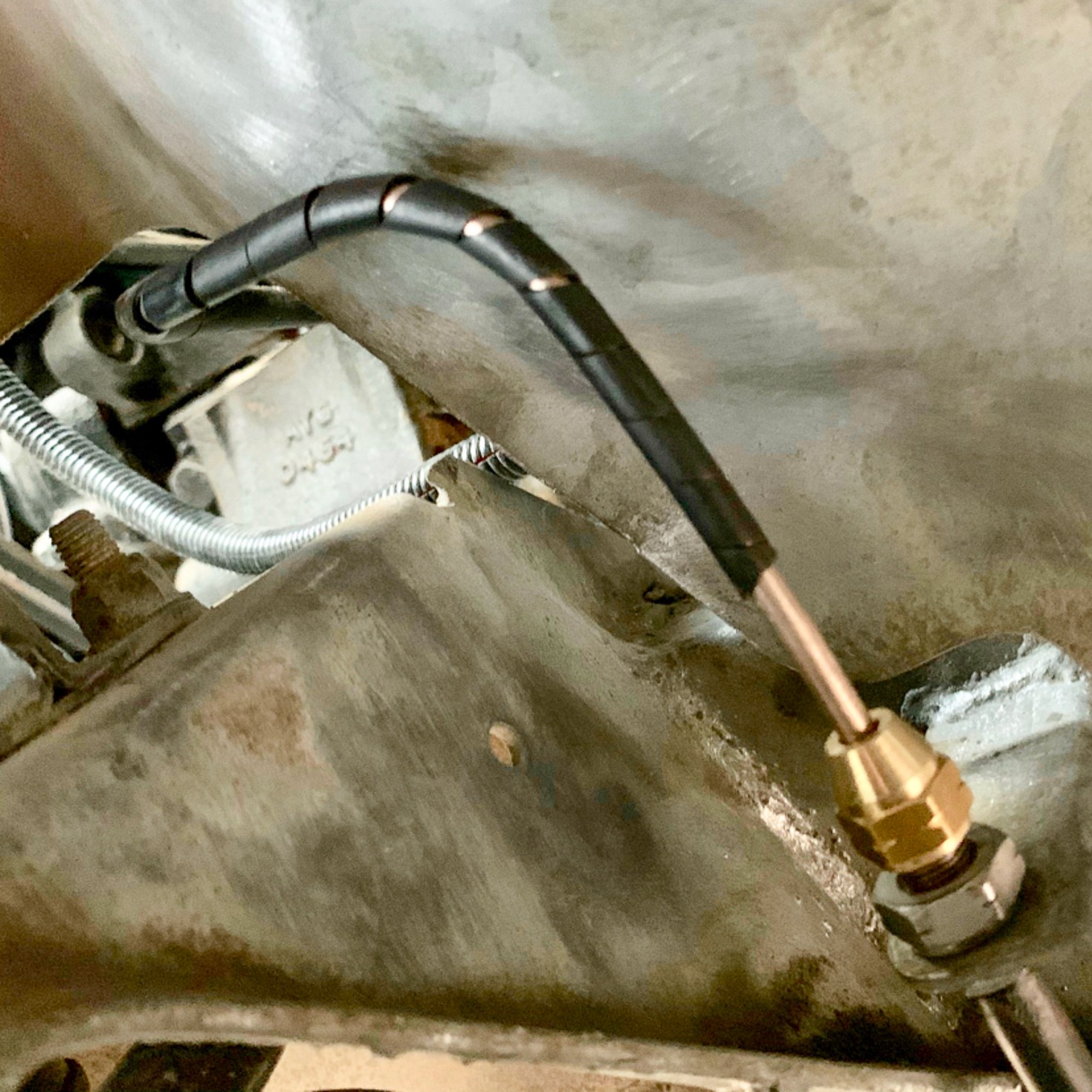
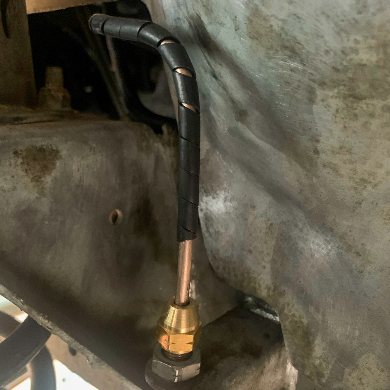
Other jobs took priority, but in the meantime I replaced all of the brake pipes in readiness; eventually the time came to do the job. I decided to replace the rear bearings at the same time and also new bearings, discs and pads on the front. The swivel joints looked good, so I would end up with a completely new bralking system and bearings – Fab!
Now this job was on the edge of what I thought I could tackle on my own, so Darren very kindly offered to help me. He was conviced that we could do it in a long day – it would have taken me a fortnight on my own, I am sure.
The day of the job arrived and Darren arrived with an assortment of parts that “may” be needed, and I hoped that I had ordered all of the other stuff correctly.
With the vehicle jacked up and supported we made a start by removing the existing rear drums.
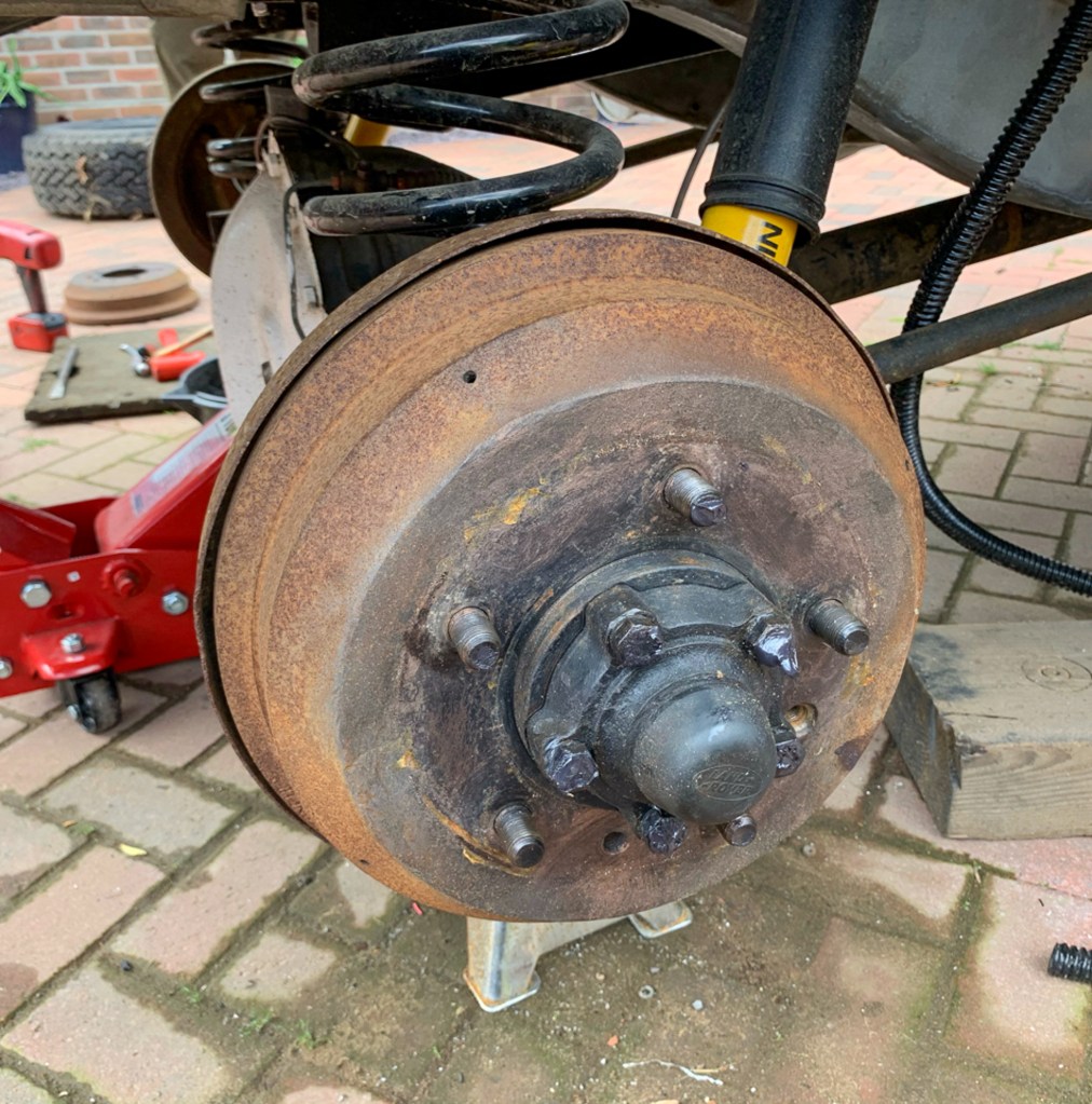
This where I would have ground to a holt on my own, as I simply did not have the strength to get to drums off as they were on VERY tight – Darren to the rescue.
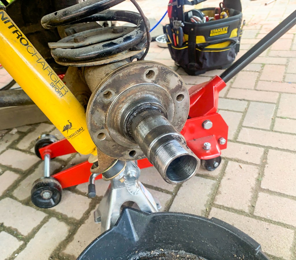
I tried to mirror on one side of the car what Darren was doing on the other, but I also had cleaning the hubs and packing the bearing with grease duties (very messy) to fulfill!
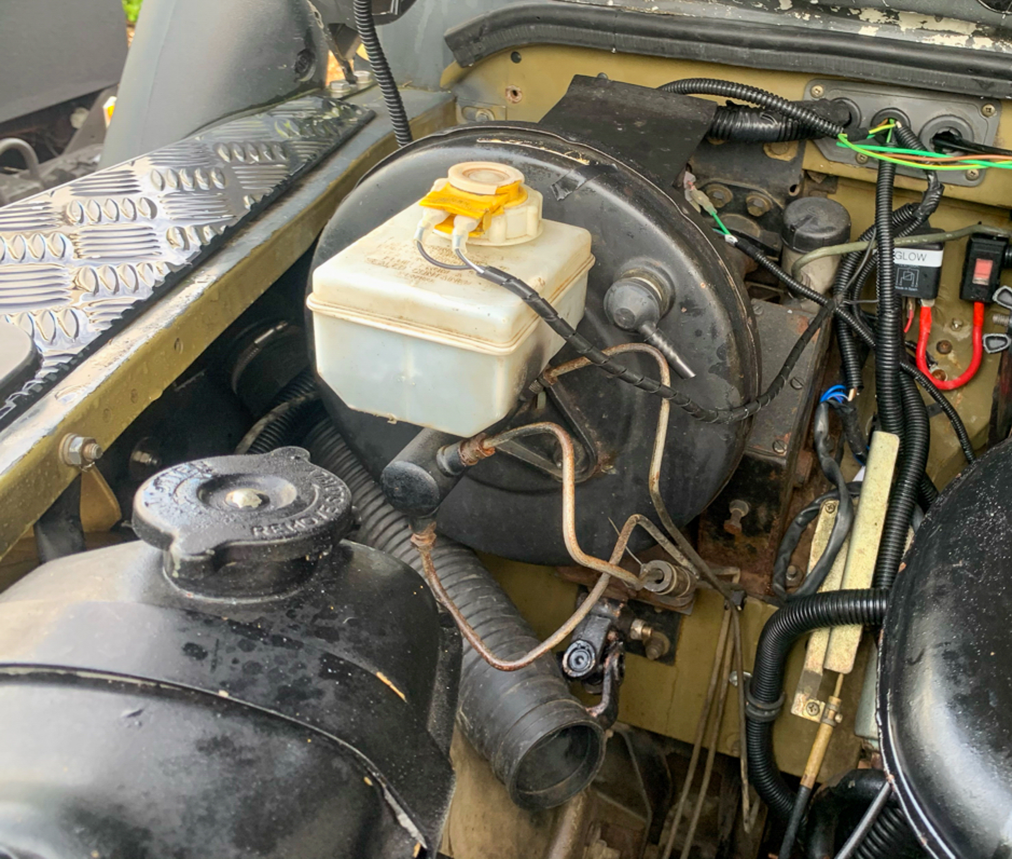
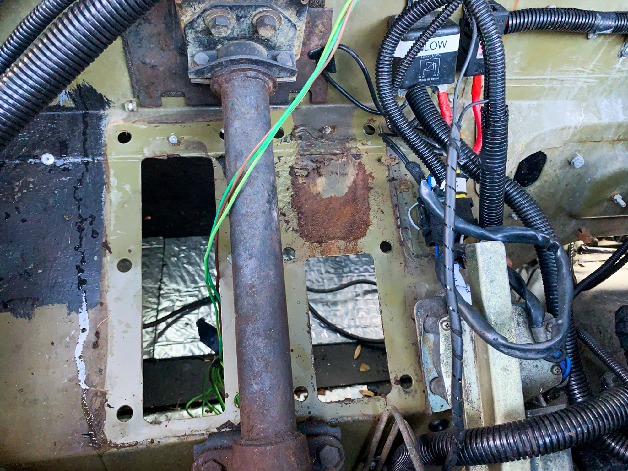
Before 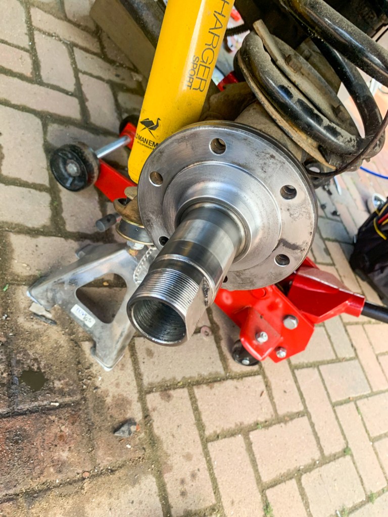
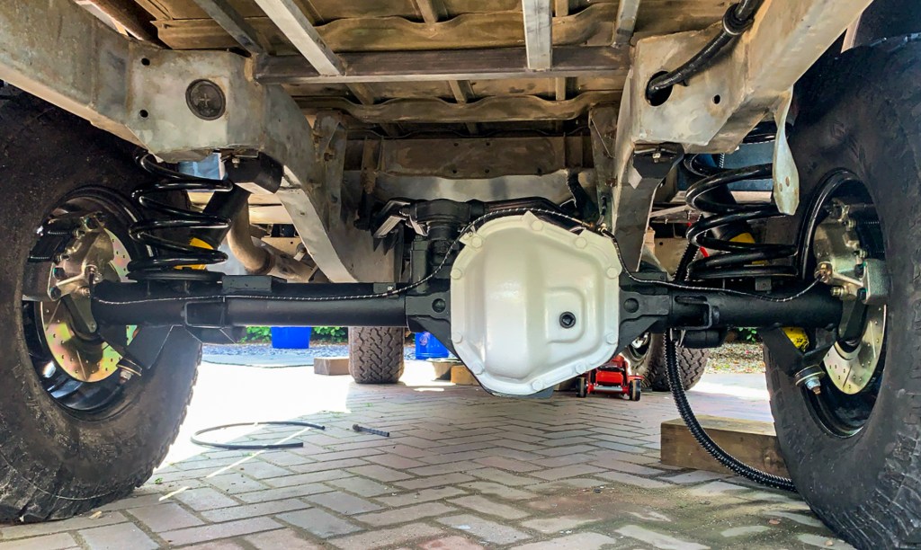
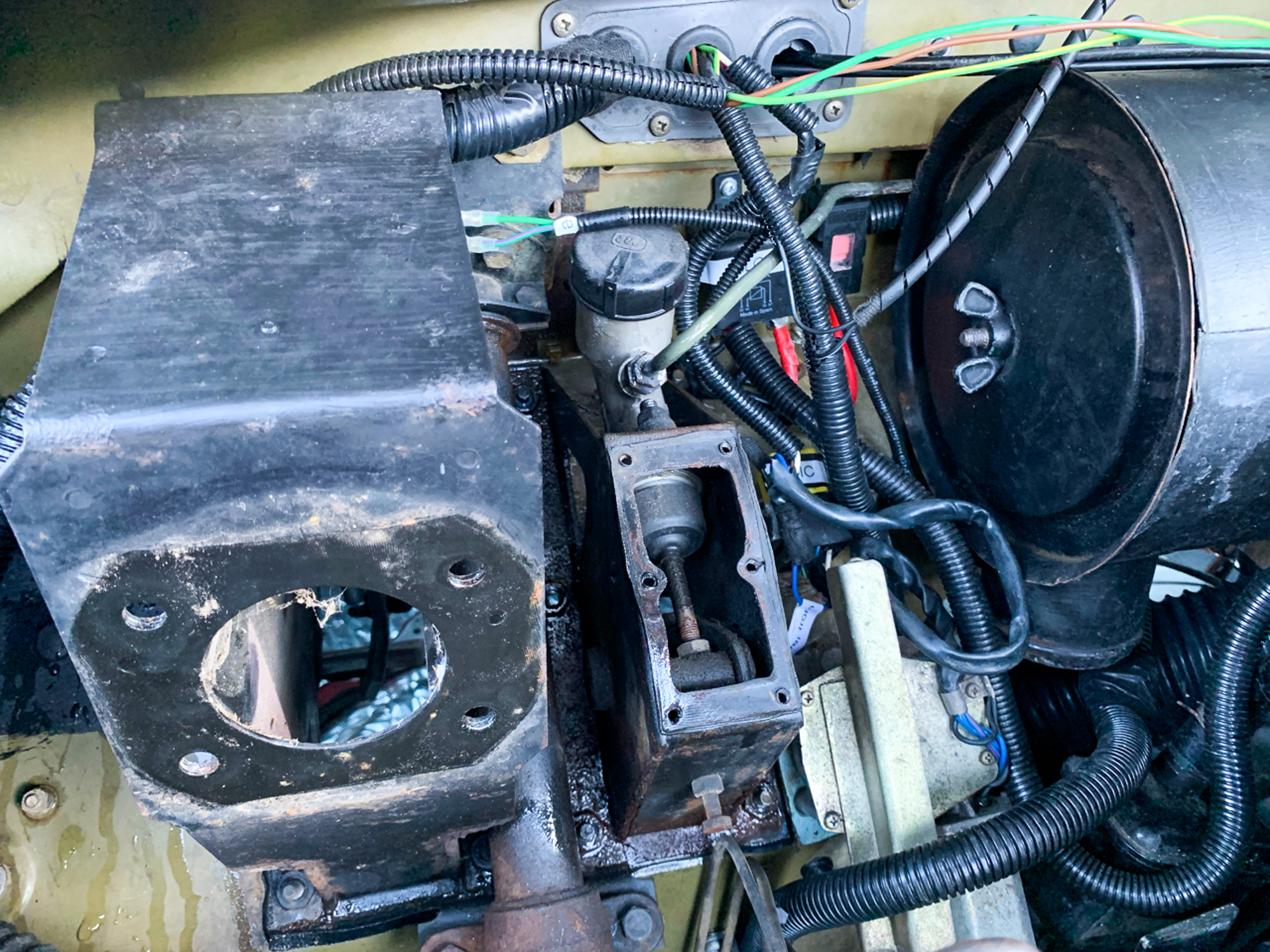
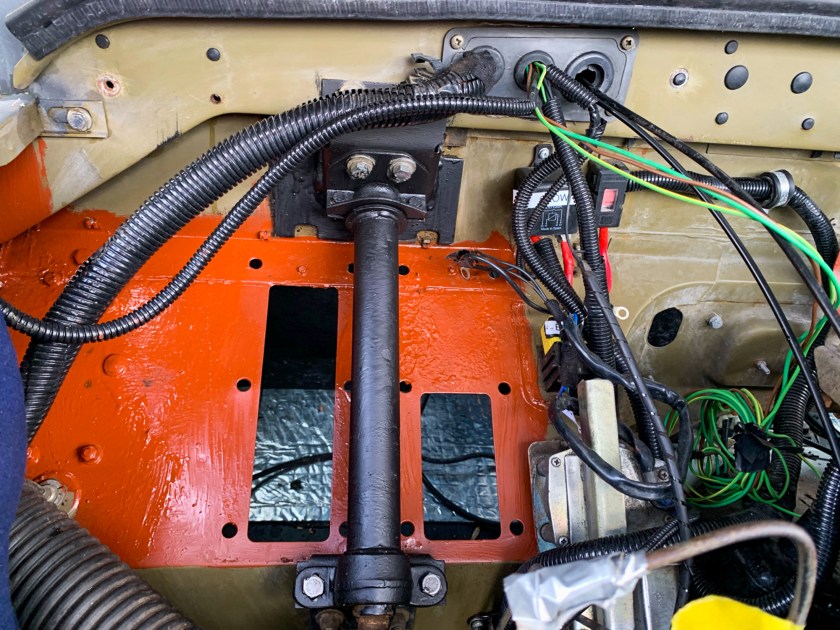
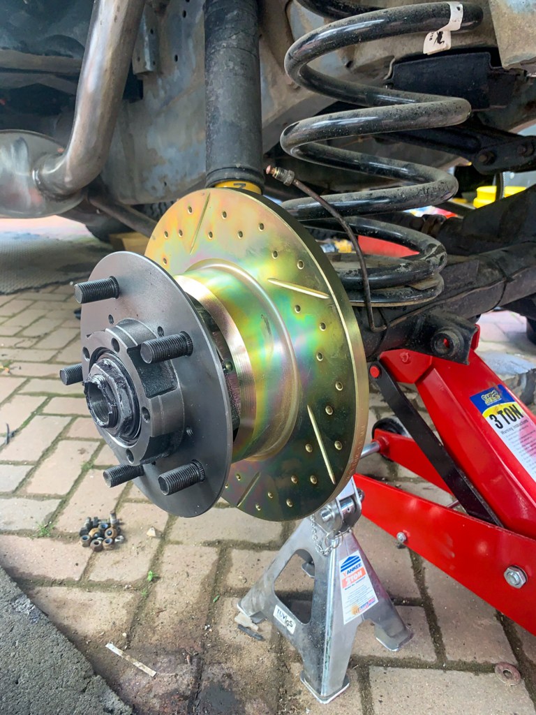
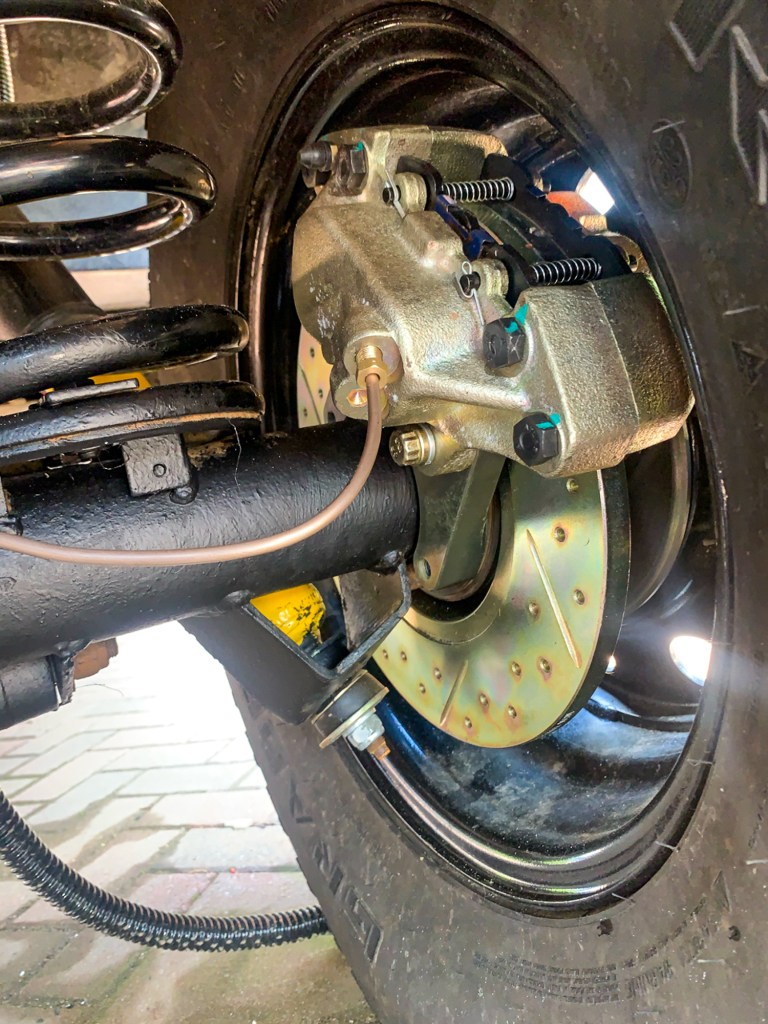
After
Then the “Special Brackets” can go on.
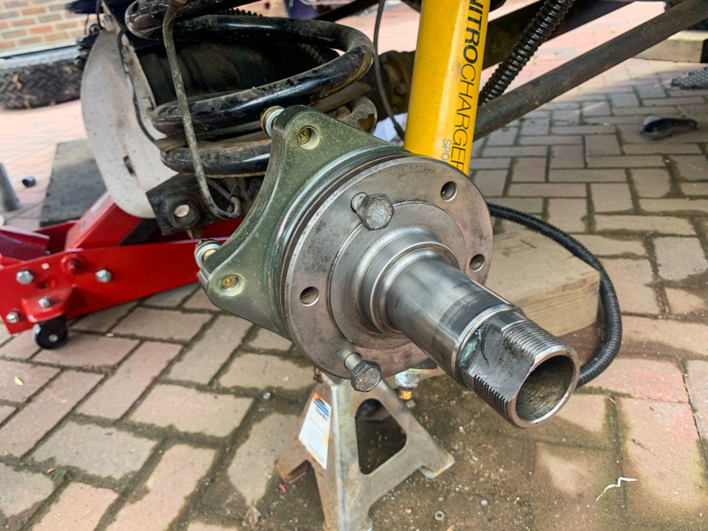

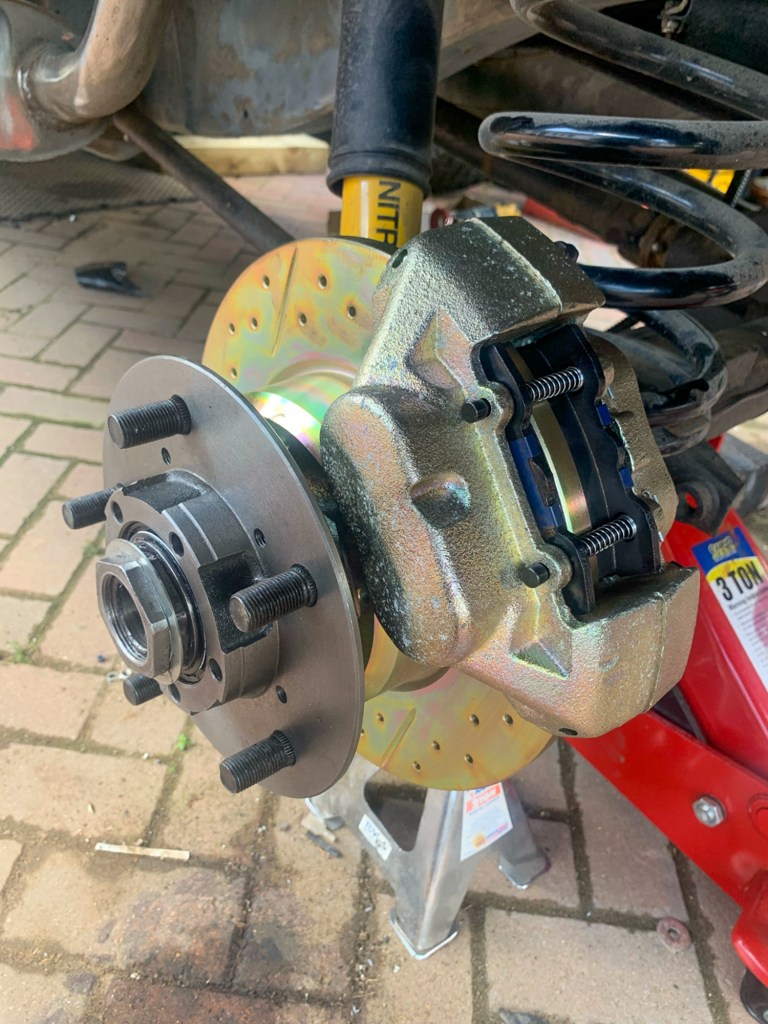
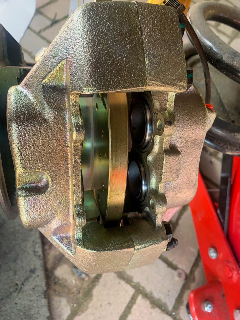
With the bearings greased up and hubs back on, the discs and calipers can be mounted.
With the rear done, it was time for lunch before tacking the same process again with the front of the Perentie.
We worked so hard in the afternoon, I forgot to take pictures, but we eventually finished by about 7.30pm – in time to enjoy a delicious supper made by Benita.
Given that my compressor had given up the ghost so we could not use Darrens pressure brake bleeder, we decided to leave bleeding through until another day.

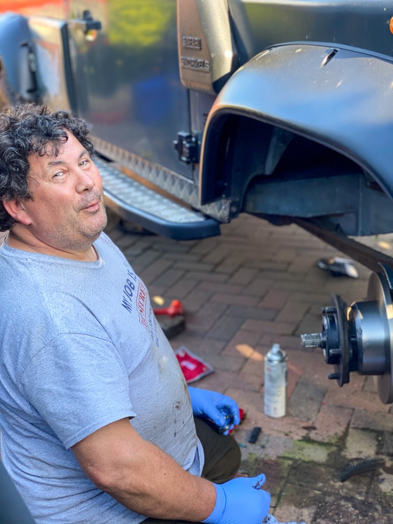
Darren 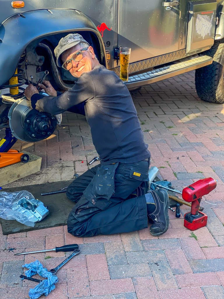
Nigel
We are both usually such organised workers, but you would not believe the number of tools scattered around the drive at the end of the day……..not to mention the empty Britpart boxes – I finished tidying up the next day.
My sincere thanks to Darren for his help on the day (and on many others!)