Well after a busy start to the year working on the Perentie, most of the major jobs are complete.
The interior is pretty much as it needs to be, we have heating, hot water, a water supply and somewhere for the waste water to go.
A toilet has been purchased, although not yet tested!
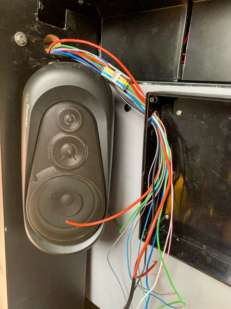
The Radio/CB/sub woofer and reversing camera works as does the dash cam that records traffic coming towards us and also traffic coming from the rear.
All of the 12v DC power works as it should and the Solar is keeping the leisure batteries and starter battery topped up. The inverter gives us limited 240v power when required.
Mechanically, everything planned has been done and we will see how that holds up. For the future we need to be looking at the drive train, we need to be able to travel at about 70mph and at somewhere between 2000 and 2500 rpm (I think) and we are only achieving about 55mph at the moment. As the clutch will need to be replaced before any major trip, it is likely that we will swap out the transfer box to give us some higher gear ratios at the same time.
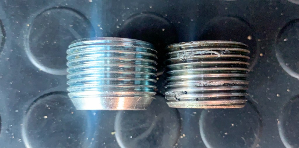
I have changed all of the fluids apart from the main engine oil which was only done last year. The oil change on the gearbox enabled me to replace the drain plug from where oil was leaking – it looks to me time the wrong one has been fitted. Also the thread looks damaged on the old one.
New drain plug on the left – definitely different.
There is one more oil leak the source of which is not obvious. I have cleaned everything down in and around the engine, so it should be easy to spot the source once we get back on the road.
I am just waiting for the front roof rack to return from the powder coaters, I can then install this and add the additional driving lights and LED scene lights for use when camping – then I will do some exterior pictures of Perentie and maybe a walk around video.
The project now is the shake everything down and get some miles on the clock in order to get the brakes bedded in. Oh and of course, to see what stops working, leaks, blows a fuse or makes an unusual noise!
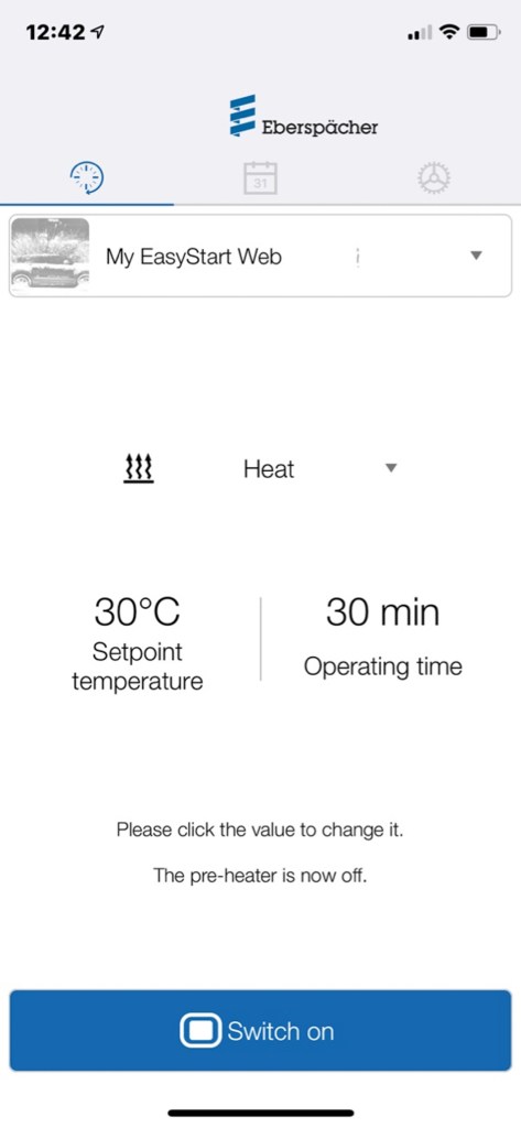
At the end of the Interior Heating post, I was considering using the Eberspacher Easystart Web App, so that we could control the heating without having to access the control panel which is in the rear of the Vehicle.
Initially I was put off by the cost – £389 for the Module and the Connection loom + an estimated 2 hours Labour at Krueger to install. I couldn’t see how difficult it could be, as I was told that it simply connected into the main heater loom. So I went ahead and purchased the module kit.
This is the point where you discover that it is not so simple, well I guess it would be simple, if you had access to all of the relevant information!
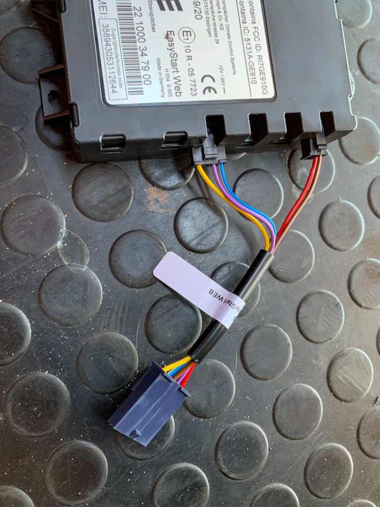
In the box, in addition to the module, was a sensor which I was told I already had, and a switch for testing the App which needed to be installed. Also present were a couple of wiring looms, some spare plugs and connectors and a booklet about how to set up the Web App.
First problem was that a dealer needs to set up the registration of the module before the App will work. Second problem, there was no wiring diagram!
This was the weekend, so I could not ring Krueger, so I interrogated Google for the wiring diagram. The result was bona fide as it was from the Eberspacher web site, I followed the instructions which initially went well with the connections to the module being made in accordance with the diagram. I then wired up the connector for the switch playing VERY careful attention to the wiring diagram and picture of the connector, to ensure the wires were in the correct order.
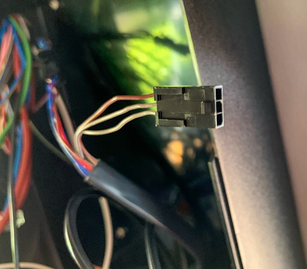
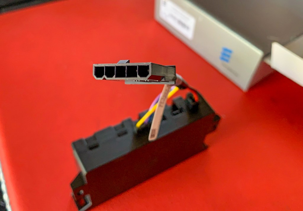
Then, at the final hurdle, the connector on the loom/flylead referred to in the instruction, would not fit the spare connection on the existing loom………..
Existing Plug in Loom
Does not fit new Connector
Because this is incorrect
Well, by now much used to frustration with these things, I waited until Monday and called Sam at Krueger, I needed to speak to them anyway, to get the App set up. I explained the wiring issue and Sam arranged for to to visit the workshop straight away to get the installation sorted – very efficient.
Once at Krueger I met with Owen who did the original install for me. It turned out that the instructions that I had found referred to the old way of installing, and the old loom/fly-lead was still supplied in the box with the modules. This was why I had to purchase another loom part which effectively splits the main wires in the existing loom to being in the web Module. You had to unplug the main control unit from the main loom and use the new loom part to connect the control unit back in and bring in the web module.
Easy once Owen had figured out that my carefully wired connector for the switch was done incorrectly – this was because even this has changed in the new set-up and i was following the diagram for the old.
The additional sensor was required despite the fact that I already had a sensor inside the vehicle; this was so the module knew the interior temperature. Anyway easily solved and the system was soon up and running.
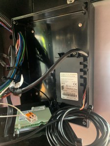
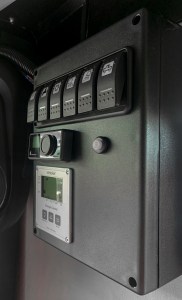
Module installed in the switch panel box, the sensor was left inside as the temperate is the same in there!Control Panel fitted.
I must admit that the final stage of authorising the App, getting the module to connect to the cloud and for it to actually control the heater was more than a bit of a Faff. Anyway we got there in the end and setting up my own account via the Eberspacher Web Site and getting the App to work on my phone was relatively straightforward.
A final issue was that it costs £32 pa for the web service, something that I did not realise until I had downloaded the App…………….
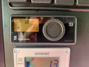
Anyway, it all seems to work so we will be able to control the heating from the front of the car, in fact from anywhere. It is also easy to set up the required interior temperature and how long the heater is on for. Also, you can set up programs so the heating comes on automatically; these I may use in the depths of Winter to stop the car getting damp and cold.
I had completed a few short trips in the Perentie, just around Hordle and to New Milton a couple of times with no drama. Planning a longer drive to speed up the bedding in of the brakes, I headed to the Fuel station at Ampress in Lymington, to top up the Diesel, as I was about 1/4 full. I had added fresh fuel during the Spring via a Jerry Can.
I started filling up and noticed the Diesel was £1.40 a litre and that was not the posh stuff! I stopped at £20 and decided that I would head for Tesco in New Milton to complete the fill up as it would be cheaper……………….I needed to go for a drive in any case.
Anyway, out on to the Main Road and I sensed a lack of power, then very quickly it started to stall as the revs dropped. Lots of revving got me over the roundabout but it still stopped on the main road. I would start but stall as the revs went on.
Its never a good time to breakdown, but it was school pick up time and busy, I was soon causing a traffic jam. Luckily 2 guys in a Discovery stopped and with the car half starting and spluttering we managed to get it off the main drag onto a service road. It was clearly a fuel problem, so I decided to bleed to system through to see if that cured it – luckily I had stacked the emergency tool kit. However, manual pump on the (new) fuel pump had seized and there was no way I could loosen it.
Now this is where a shakedown is critical…….preferabely near home! My phone was running low on battery, no problem I thought, plug it in to the onboard USB. Didn’t work, which was odd as I had tested the sockets – later it turned out that the lead I had got from an authorised Apple dealer would connect to a computer, but not charge……………
So I called Benita who came to rescue me, lucky I was only a few minutes down the road. Double lucky as I had just changed my insurance and thus the breakdown cover; and although I thought I had, I had not programmed the number into my contacts on the phone, so i couldn’t call the breakdown anyway.
Back at home, I charged to phone a bit, and called the breakdown. In the meantime I called Darren at Milford Motors to say that I was dropping the car down, only to be told that they were closed for a while……….Oh No!
Ever helpful, Darren gave me the number of Arron at AJH Motors in Sway, a mate of his. Arron said I could drop the car down and come down with the keys the next morning.
Luckily the breakdown called out was Forrest Rescue in nearby Milford on Sea, so we got the car to Sway and I was back home in less than an hour – just in time for a G & T.
Although I could have tried to sort the problem, the small print on the insurance company paperwork, basically said that they would take a dim view of a call out for a similar issue, if you could not prove that you had taken steps to sort the problem. i.e. they might not come and get you! So I needed proof.
I called to see Arron the next morning and ran through the issues, making sure he knew about the hidden filter in the fuel line Banjo bolt in the inlet side of the fuel pump. Luckily, Arron said he look at the car immediately.
The diagnosis was water in the fuel, Arron cleaned the sedimenter, cleaned the hidden filter, which did have some debris in there and changed the fuel filter. I assumed that the water had got in during the winter, often the bonnet was open when it was raining, as I was doing other jobs. Odd though, that I had completed a few previous journeys with no problem.
A few days later with the Perentie running perfectly, I saw Neil Reid in New Milton when I was getting my heater sorted. He asked how it was going and I told him of the breakdown, but not the reason. Anecdotally, he said that he too had had an issue a few days previously as well. He had topped up with diesel at Burley Services and had stopped a mile down the road with symptoms the same as mine.
He had got a Mac Donalds at the services so he just sat for a while and enjoyed his food. Then his van started, no problem and he drove home. These stations are near and any delivery truck may well have visited both – dodgy fuel anyone!
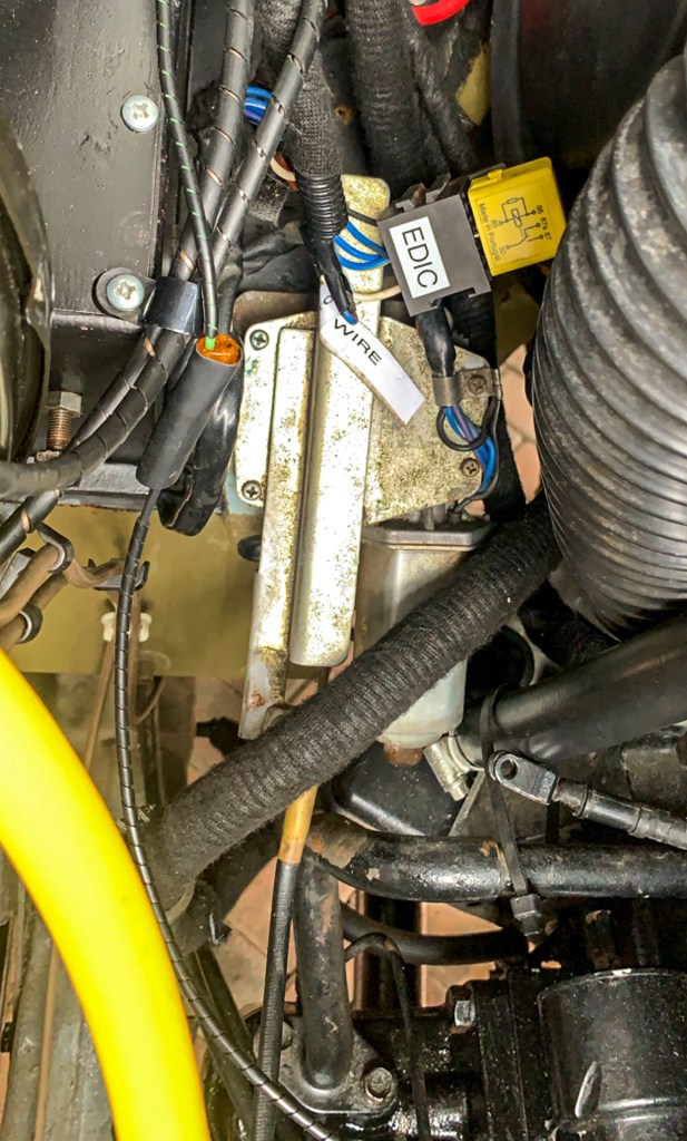
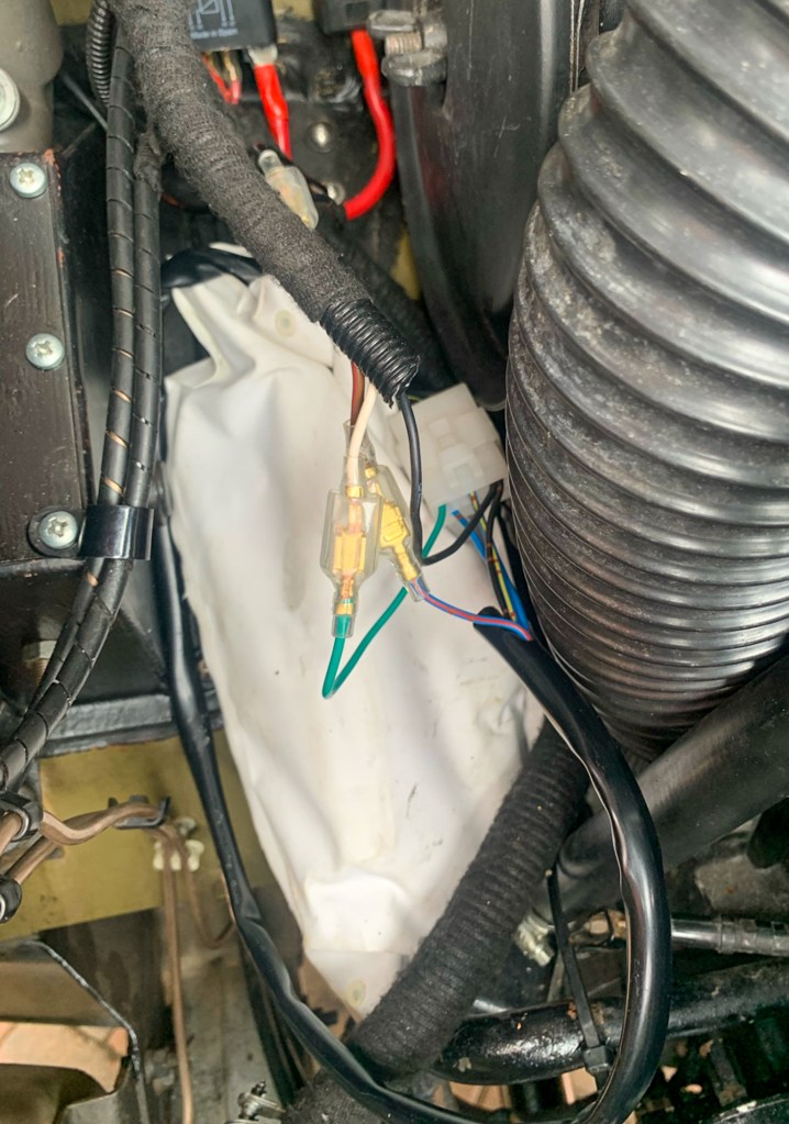
The Electric Diesel Injection Control is basically a motor that controls a fuel on/off soledoid, that prevents the engine from being started accidently.
The motor operates a wire which turns on the fuel when the ignition is switched, you can hear a re-assuring whirrr……..when it is working correctly!
You may recall me mentioning this in an early post, when we had problems getting the vehicle to start/run correctly – it turned out that the valve was not opening fully, thus restriciting the flow of diesel and was the cause of those issues.
Back then, we tracked the fault to a dodgy and very badly wired relay. In fact subsequent investigation uncovered wiring that was so poor, the entire vehicle was re-wired!
During the re-wire we provided a new fused permanent feed to the EDIC along with a new fused ignition feed, again via a relay. Everything seemed OK and when we were stopping and starting the vehicle during the re-bulld everything worked fine. That was, until we actually started using the car again on the road.
After a couple of runs, the engine either struggled to stop or refused to stop altogether. i.e. the solenoid was not closing off the fuel, so this had to be done manually. Sometimes, it would just “hunt” cycling between on and off. This time I knew it was not the wiring or the various relays – it had to be the EDIC motor itself………….
EDIC Motor in Situ
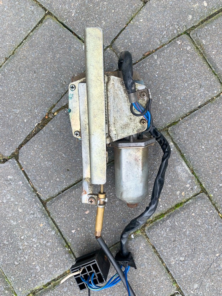
EDIC Removed
Extremely annoying as I had replaced all of the other engine ancillaries and had been working around the EDIC motor for months. More than once, I thought I should replace it, but it was very expensive, had to be imported from Australia, and Hey – the one I had was working! – I should have known better.
I had to bite the bullet and ordered the part BYG9369 and associated wiring from Brad at KLR in Australia – A$586 + A$90 shipping and 20% duty on arrival in the UK – Ouch……….
On a positive, the package arrived in a week with the motor looking very smart in its white vinyl bag to protect it from the elements. My original had no such protection.
Fitting, at least initially, was relatively straightforward despite it all being a tight fit, now the clutch slave cylinder was back in. Annoying I had to remove some of the carpet that I had just fitted to get to the main bolts., but that done I just had to connect the live, ignition feed and the earth.
A quick test confirmed that the motor was working correctly.
The new EDIC Installed
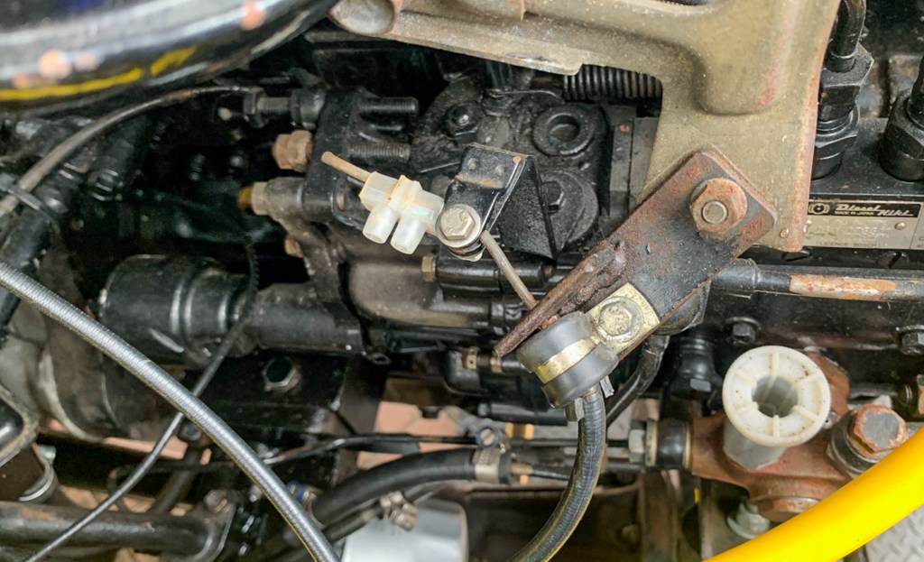
The next job was to connect the Bowden cable to the fuel cut of switch on the engine. The cable on my existing motor was less the 30cm long and went directly to the switch on the engine, the cable on the new motor was in excess of 90cm which I thought odd.
My friend Darren checked his Perentie and it turns out that the cable should take a longer and more relaxed route to the switch by looping under the fuel pump.
Like everything else on the vehicle someone in the past who did not have the correct parts just made the best of what they had. In this case it was the way that the cable was connected to the fuel cut off switch, via makeshift braket on the engine to hold the Bowden cable in place and a old piece of cable block.
A old cable connecter holding the wire in place
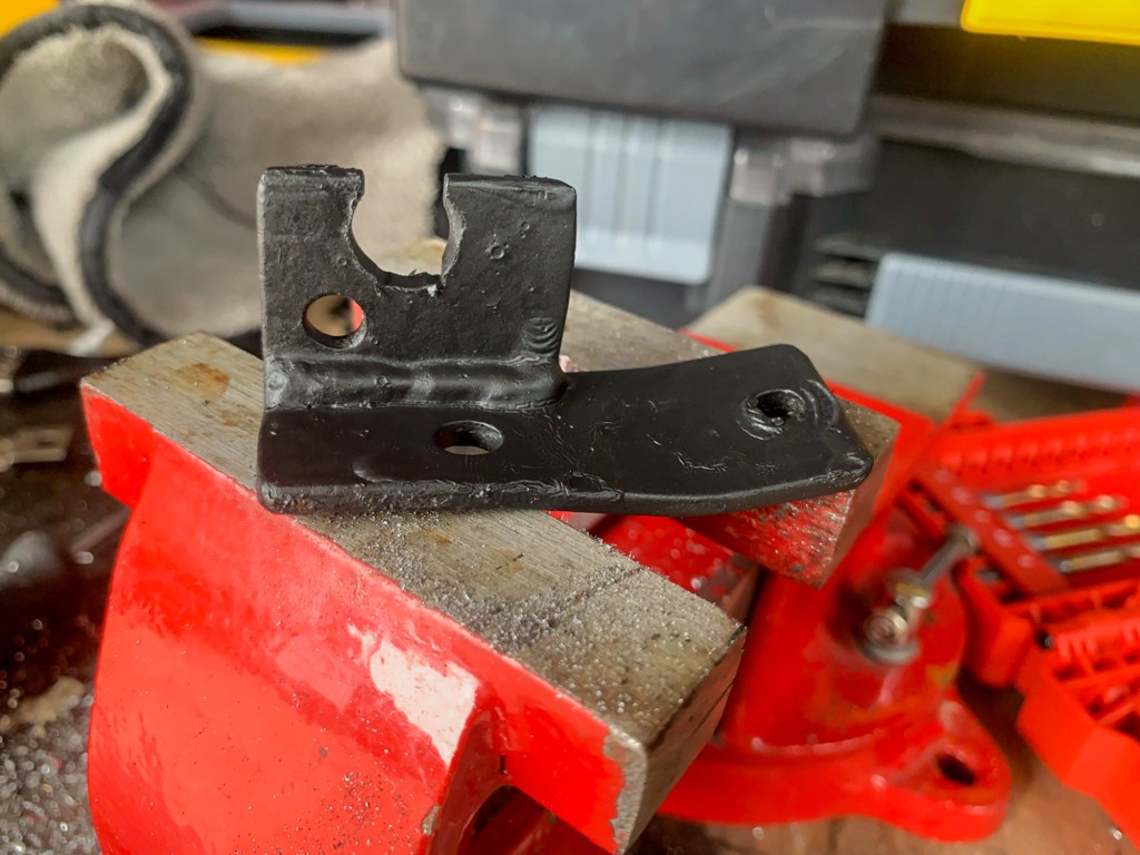
Best way forward was to figure a way of connecting the new cable to the switch. First idea was simply to drill a bigger hole in the bracket for the new cable. However, the “T Bar” fitting on the end would not pass through the adjuster nut on cable, so that was not going to happen.
So, instead I cut a groove in the bracket and solved the problem that way.
Amended Bracket
The original Perentie set up is different, and has a special bracket to do this job; i have no idea of the part number of even if they are available, hence the work around.
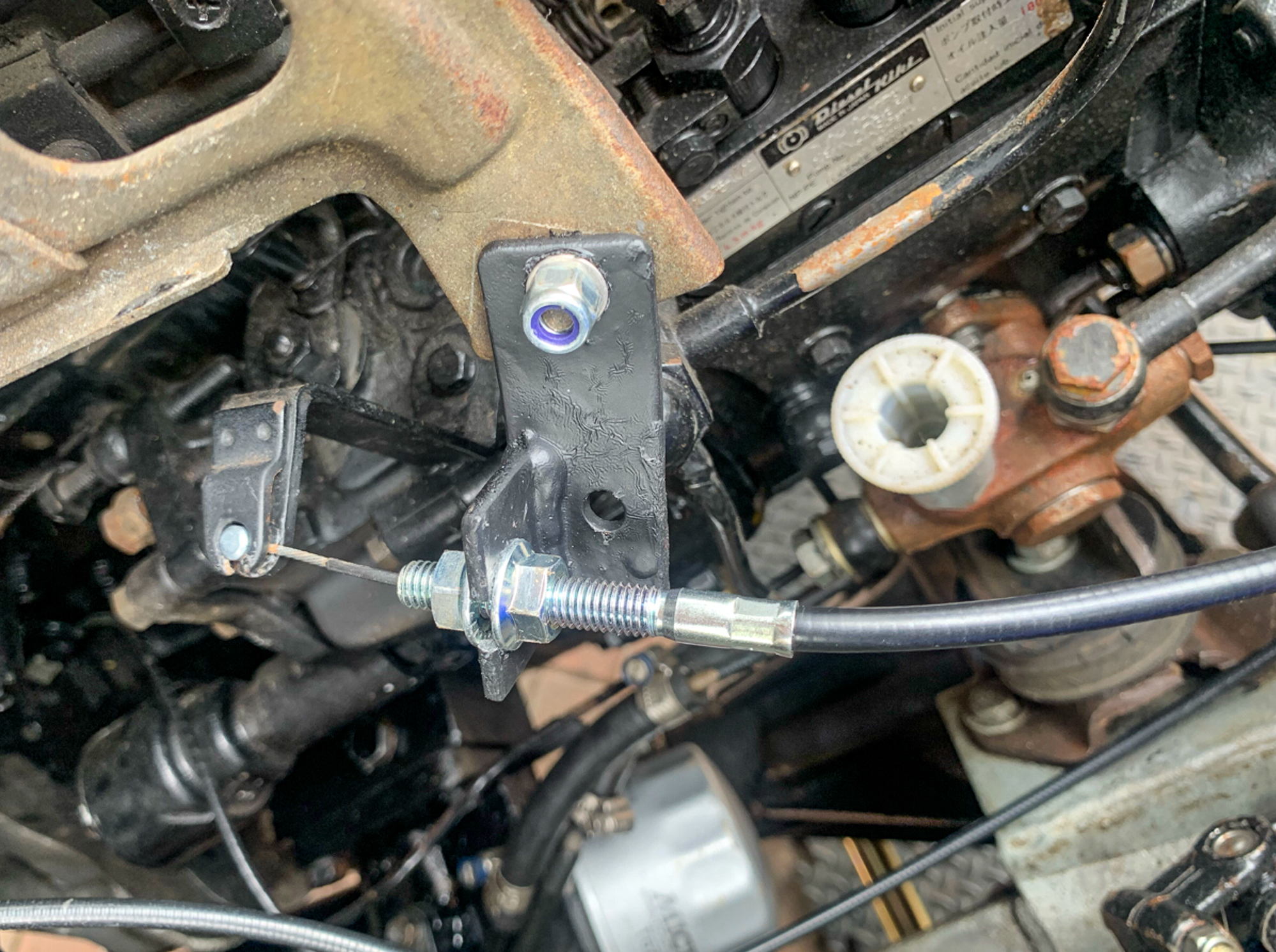
After some adjustments, I found a spot where the engine would start and stop correctly. So I locked it into place. I suspect, the cable may give a little in use, and that a small adjustment might be needed in the future.
New cable in position.
In an emergency, I can just disconnect the cable and allow the switch to stay in its default “On”position so the engine will still run. Turning off will require lifting the bonnet to pull the switch back by hand.
In reality the EDIC is a motor that simply moves a cable a few centimetres when the ignition is activated; i am not expectig to replace this again!
This particular job has been in the planning stage for at least 18 months…………
Shortly after purchasing the Perentie I knew that I wanted to upgrade the rear drum brakes to discs. There was no conversion kit available in the UK and the only option would be to swap the whole axle, maybe from a Discovery 1. I wanted to retain my strong Salisbury axle, so this was not an option.
My friend and Land Rover afficianado Darren pointed me in the direction of KLR Land Rovers in Australia, the same outfit from which I was sourcing the Water Pump and related parts. KLR make a specially machined hub and bracket than enables the discs to be bolted on to the Salisbury rear axle. I had discs on the front already.
The parts were ordered up and have been sitting on the shelf since January 2021.
Other jobs took priority, but in the meantime I replaced all of the brake pipes in readiness; eventually the time came to do the job. I decided to replace the rear bearings at the same time and also new bearings, discs and pads on the front. The swivel joints looked good, so I would end up with a completely new bralking system and bearings – Fab!
Now this job was on the edge of what I thought I could tackle on my own, so Darren very kindly offered to help me. He was conviced that we could do it in a long day – it would have taken me a fortnight on my own, I am sure.
The day of the job arrived and Darren arrived with an assortment of parts that “may” be needed, and I hoped that I had ordered all of the other stuff correctly.
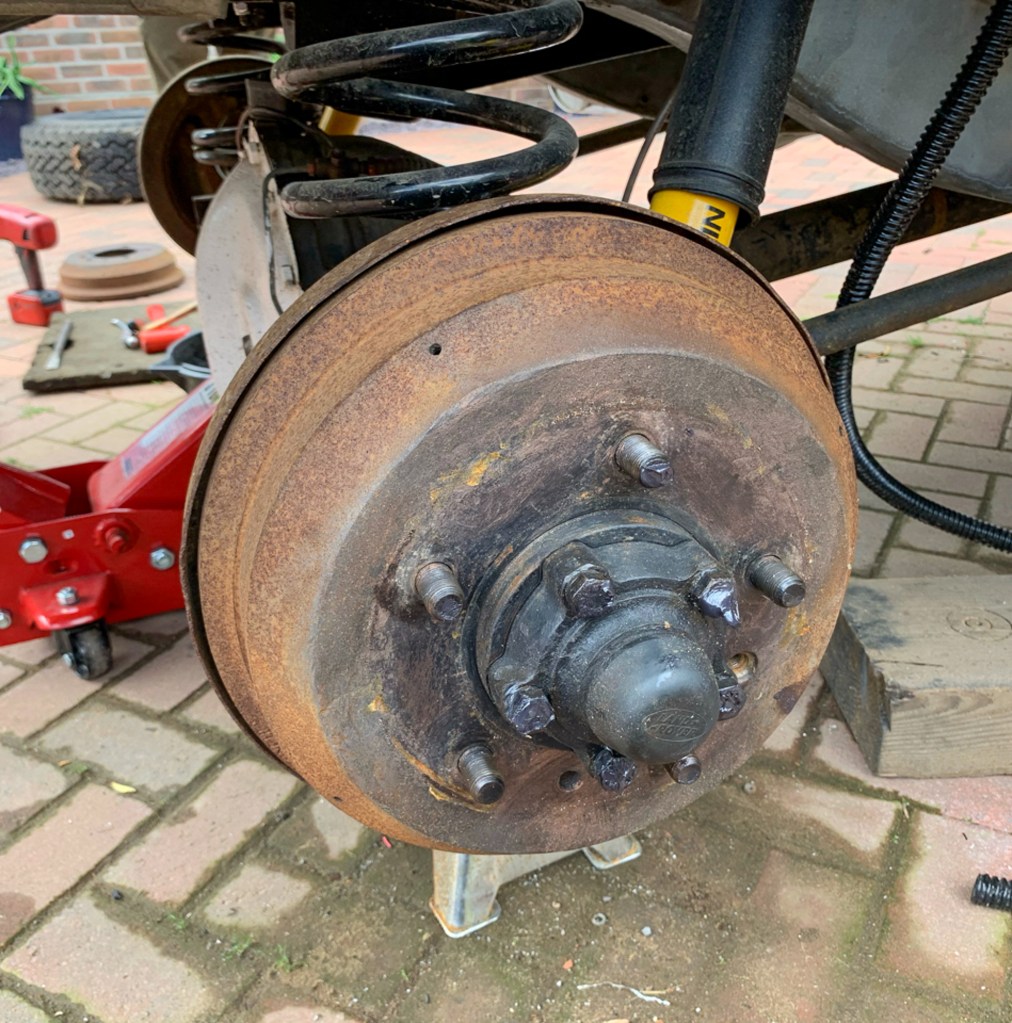
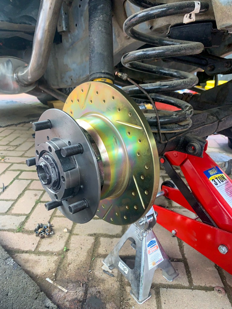
With the vehicle jacked up and supported we made a start by removing the existing rear drums.
The starting point.
This where I would have ground to a holt on my own, as I simply did not have the strength to get to drums off as they were on VERY tight – Darren to the rescue.
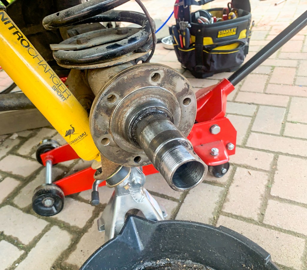
I tried to mirror on one side of the car what Darren was doing on the other, but I also had cleaning the hubs and packing the bearing with grease duties (very messy) to fulfill!
Before
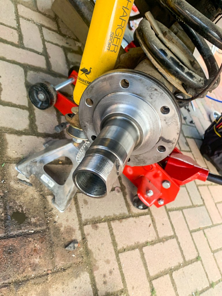
After
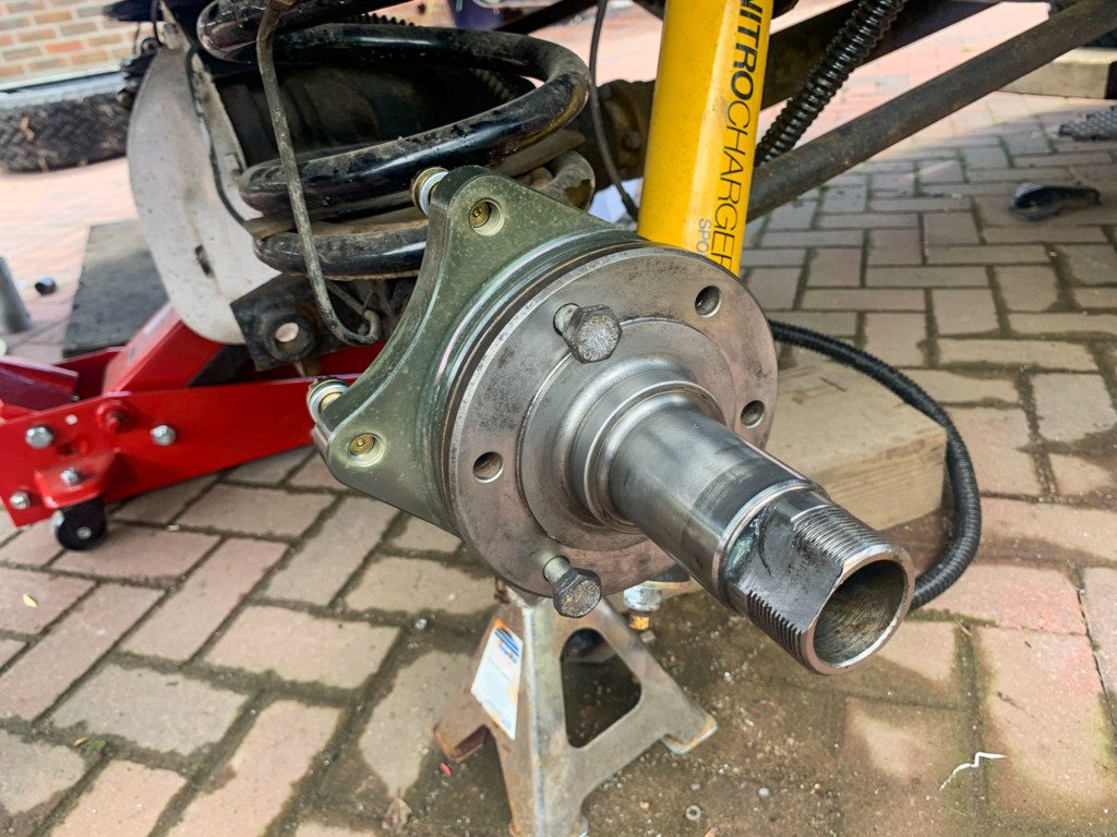
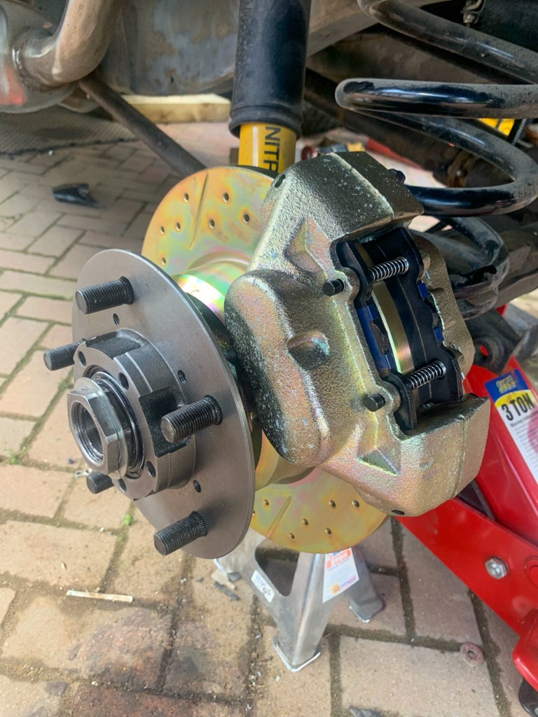
Then the “Special Brackets” can go on.
The brackets that enable the calipers to fitted to the Salisbury Axle.
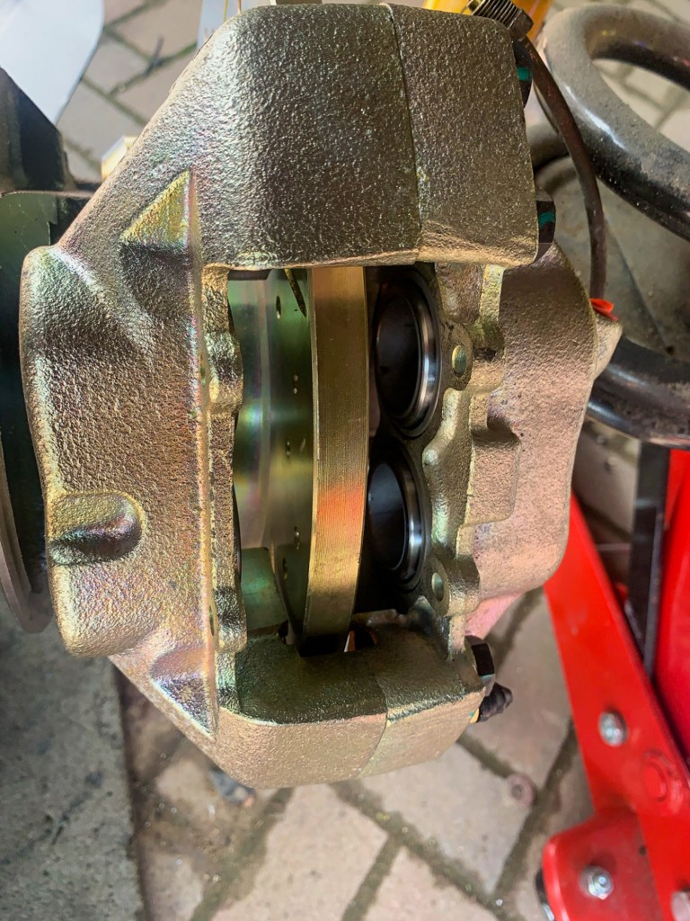
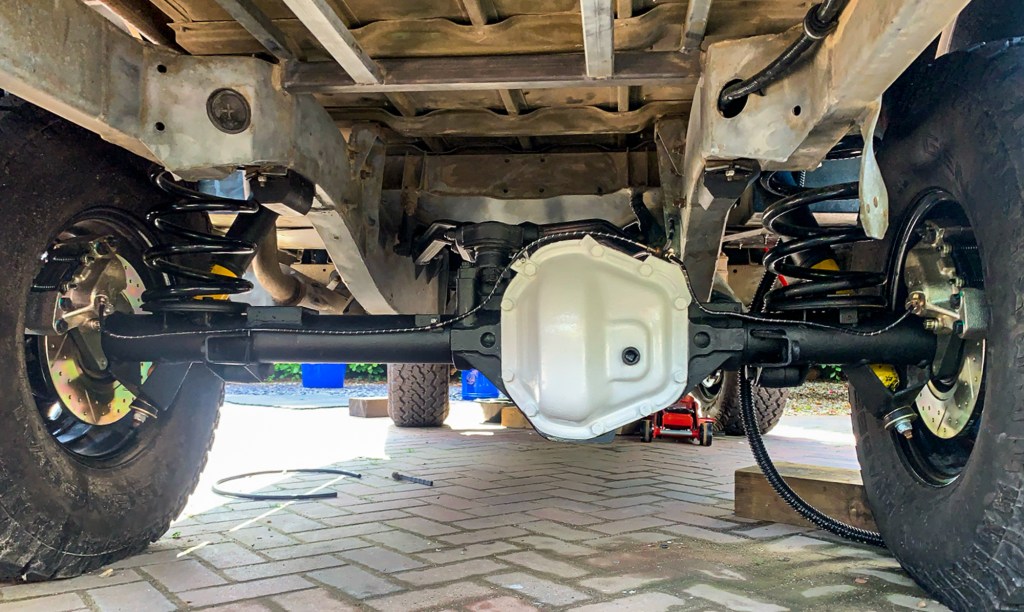
With the bearings greased up and hubs back on, the discs and calipers can be mounted.
All looking very smart
With the rear done, it was time for lunch before tacking the same process again with the front of the Perentie.
We worked so hard in the afternoon, I forgot to take pictures, but we eventually finished by about 7.30pm – in time to enjoy a delicious supper made by Benita.
Given that my compressor had given up the ghost so we could not use Darrens pressure brake bleeder, we decided to leave bleeding through until another day.
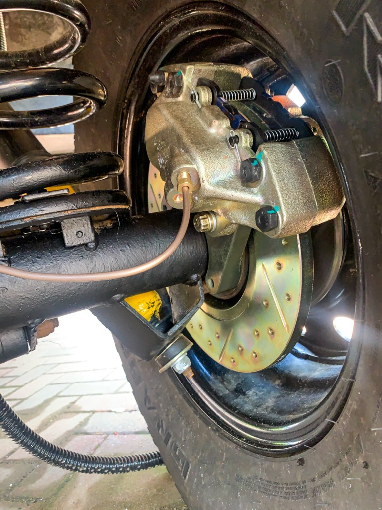
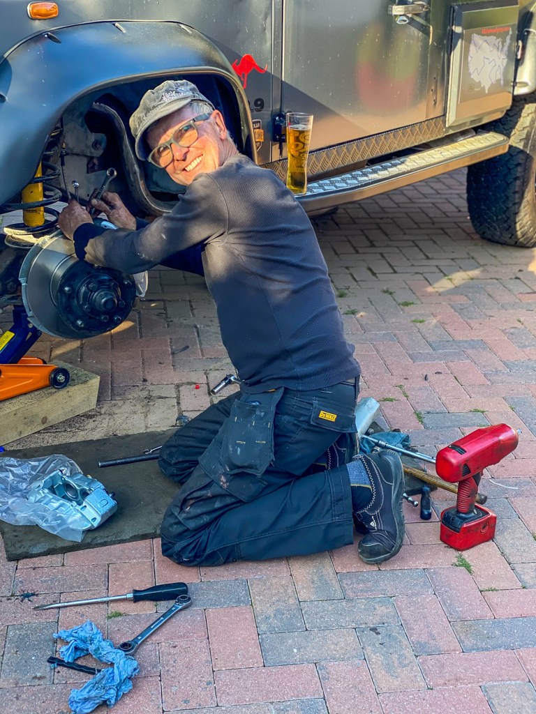
Rear brakes from the underneath.
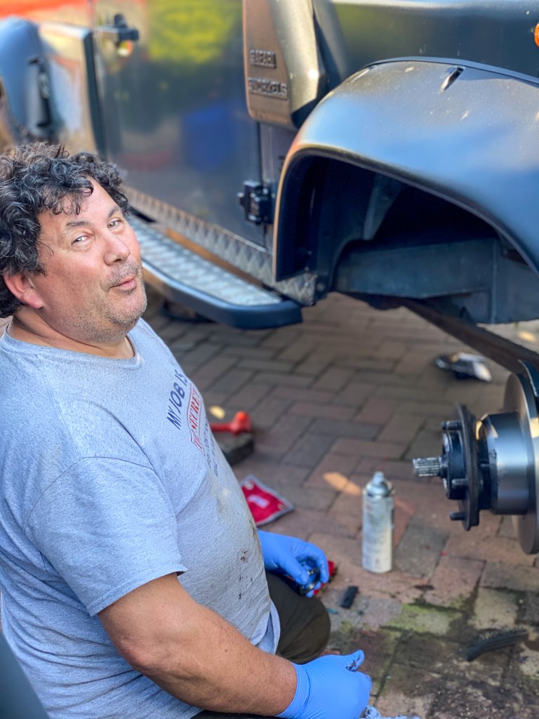
Darren
Nigel
Organ Grinder and Monkey!
We are both usually such organised workers, but you would not believe the number of tools scattered around the drive at the end of the day……..not to mention the empty Britpart boxes – I finished tidying up the next day.
My sincere thanks to Darren for his help on the day (and on many others!)
Now, I am no Plumber and I don’t like Plumbing – but what I do know is that water is not dissimilar to electricity in the way that it flows. Oh, and it won’t give you a shock or cause a fire………..
So I drew a plumbing diagram, like a wiring diagram.
I knew I needed a sink with hot and cold water and the same for a shower output. I just needed to get cold water to both and to the water heater and from the the heater, to the sink and the shower – simple….
Well it would have been if you were not trying to install it in a Land Rover, but at least I had a plan.
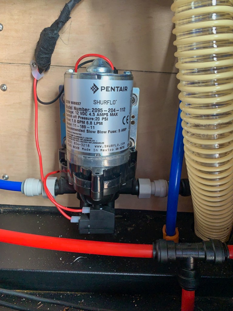
The water tank was going under the vehicle where spare wheel was mounted – the water heater would just fit into one of the side lockers. The filter and expansion tank would go into another side locker and the pump in a cabinet inside the vehicle – just need to connect them up…………
I decided to use John Guest fittings as they were east to fit and virtually leak proof when connected – once I worked that they do not work with standard (blue) water pipe we were away.
There are a number of options for heating water, most are designed for larger vehicles and run on gas; others heat the water from the engine and I did not want to run pipes (which would be vulnerable to damage) from the engine to a calorifier.
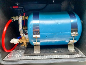
I sourced a small (6 litre) water heater from Surejust whch would just fit in the side locker. This unit works on 12v DCand 240v on an immersion basis. The idea being that you heat the water whilst travelling from a 12v DC circuit. The insulated tank then keeps the water at a reasonable temperature for 24 hours – we will see. With a hook up, no problem as the 240v supply will give us constant Hot Water.
Surejust Water heater
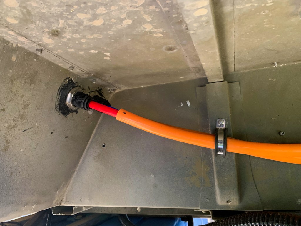
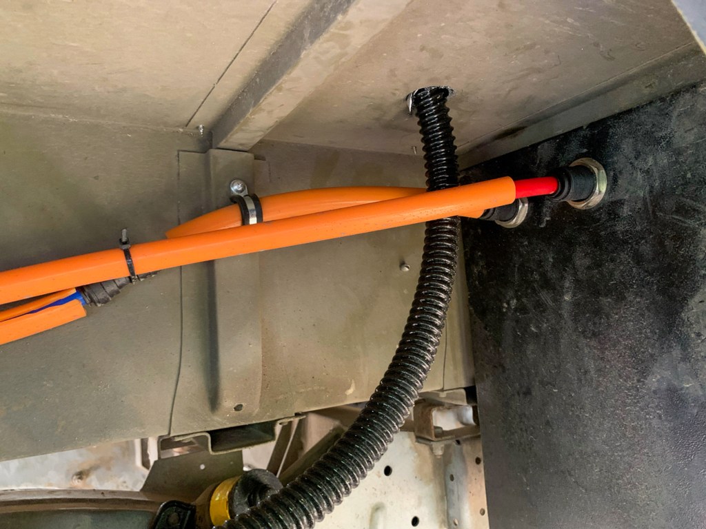
The cold supply to the heater and the hot water (via an expansion tank) back had to run underneath the vehicle to prevent the drilling of even more holes in the vehicle.
Getting water supply to the Heater and back
I used bulkhead fittings to get the pipes through the body, though this meant that the pipes were a little longer than I would have liked, as you need some slack to able to make the connnection. I learned the hard way as the first connections leaked and I had to make the pipes a little longer so they clicked in properly. They are nowhere near the wheel travel, so I should be OK.
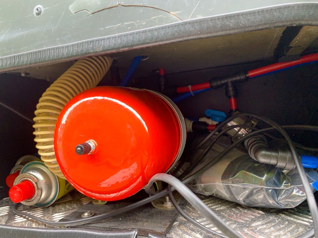
Expansion tank, filter and isolater valve.
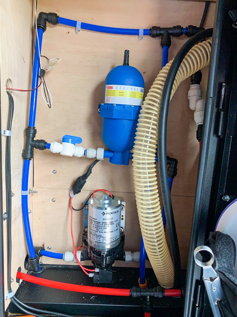
Inside, pipes were run up from the water storage tank into the pump and out via an accumulator tank to the sink/shower and heater. Likewise the hot return goes off to the sink and shower.
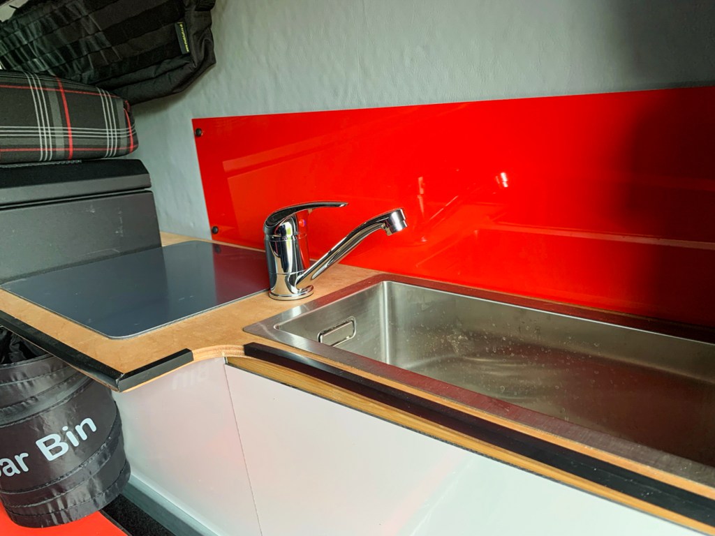
I went for a larger sink, so a least it would be of some use – no point if you can only fit a cup in it! – a nice stainless steel one from Amazon and a mixer tap with John Guest connections was sourced.
I am no carpenter either, but I managed a reasonable job of making a frame and a worktop – given that everything was a bit wonky and it was difficult to get a good fixing. This can aways be re-done in the Winter now I know the measurements.
The splashback, worktop protection and the cupboad fronts which have magnetic catches are are an aluminium composite which can be ordered in exact sizes from Sheet Plastics.
The cupboard fronts were a pain, the first trial was with plywood, whch was too heavy – I then used these as a template for the composite.
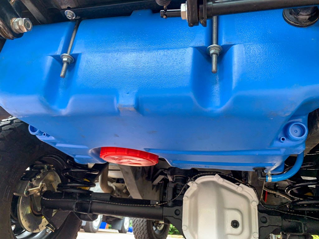
When looking for a water tank, it turned out the standard Fiamma one fitted the space perfectly; I know its blue, but I figured that it would look worse if I painted it it, when the paint started to come off…………
I fitted the water tank one weekend using the metal straps supplied – then decided that it did not look right, also the tank had a tendancy to move slightly and I could not get it to tighten sufficiently.
When the vehicle was with Neil Read for the heater fit (more of that later) I asked him to make up some brackets for me – as usual he did a splendid job.
I purposely fitted the tank upside down so I could use the big red cap to empty and clean – this meant adding the nut-in fitting in slightly different locatiosn to the ones that Fiamma suggested. I also fitted a level guage and a heater, in case we encounter low temperatures a some point – maybe in America.
Wiring for the heater and level monitor. You can also see the fitting for the filler and the output at the bottom.
After having connected up most of the 12 v circuits, I needed a way of switching them.
A couple of circuits were sent to the front of the vehicle to be switched from the Centre Console – for example, one of the rear lights for reversing and an on/off for the water heater. I also needed a place for the control panel for the Votronic DC to DC charger.
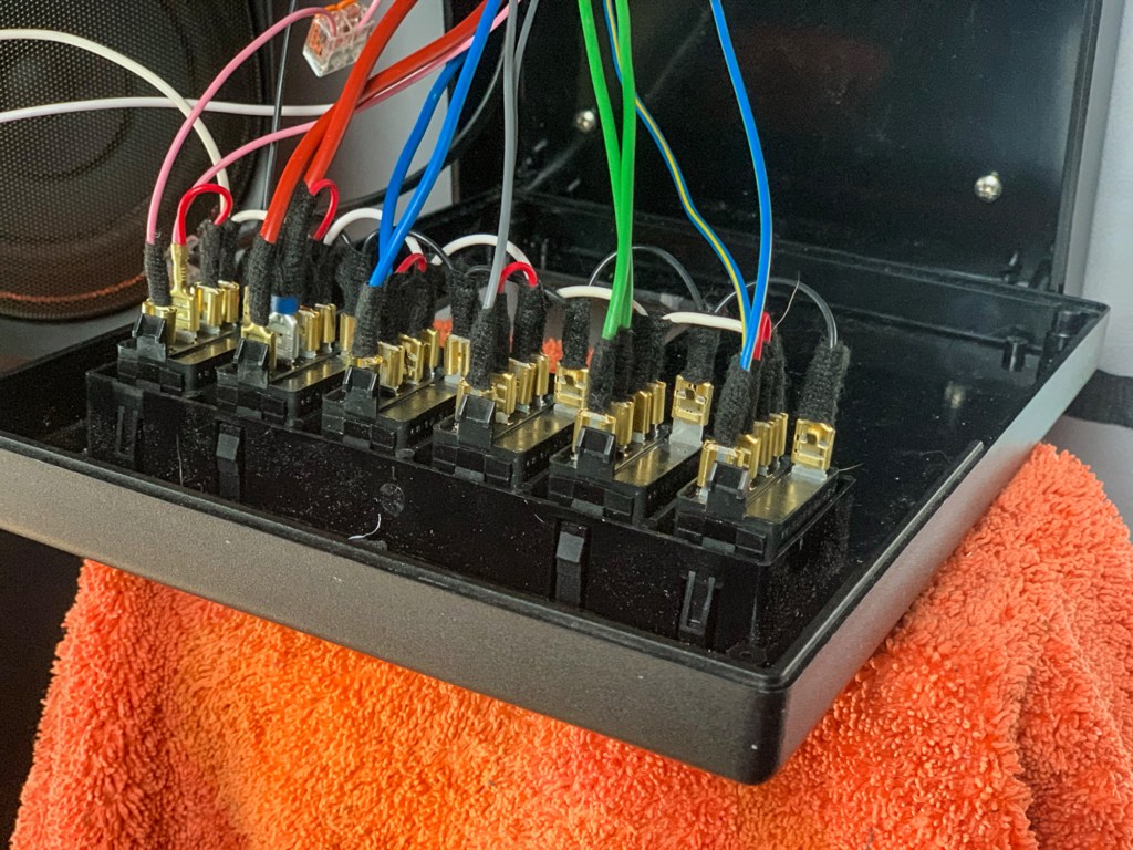
I could not find anything off the shelf, so in the end measured up and sourced a black adaptable box in the correct size. Mud Stuff sell a panel for Carling Switches, so I got that and 6 switches to install in the box.
Preparing the Adaptable Box
Getting the cables to the box
Bringing the wires to the box position was straightforward, a couple were a bit short and needed lenghtening. At this stage making careful notes of the colours for each circuit.
Connecting the switches
Completed Job
I left a bit of space, as I knew I would need a location for a water level guage and the control panel for the heater at a later date.
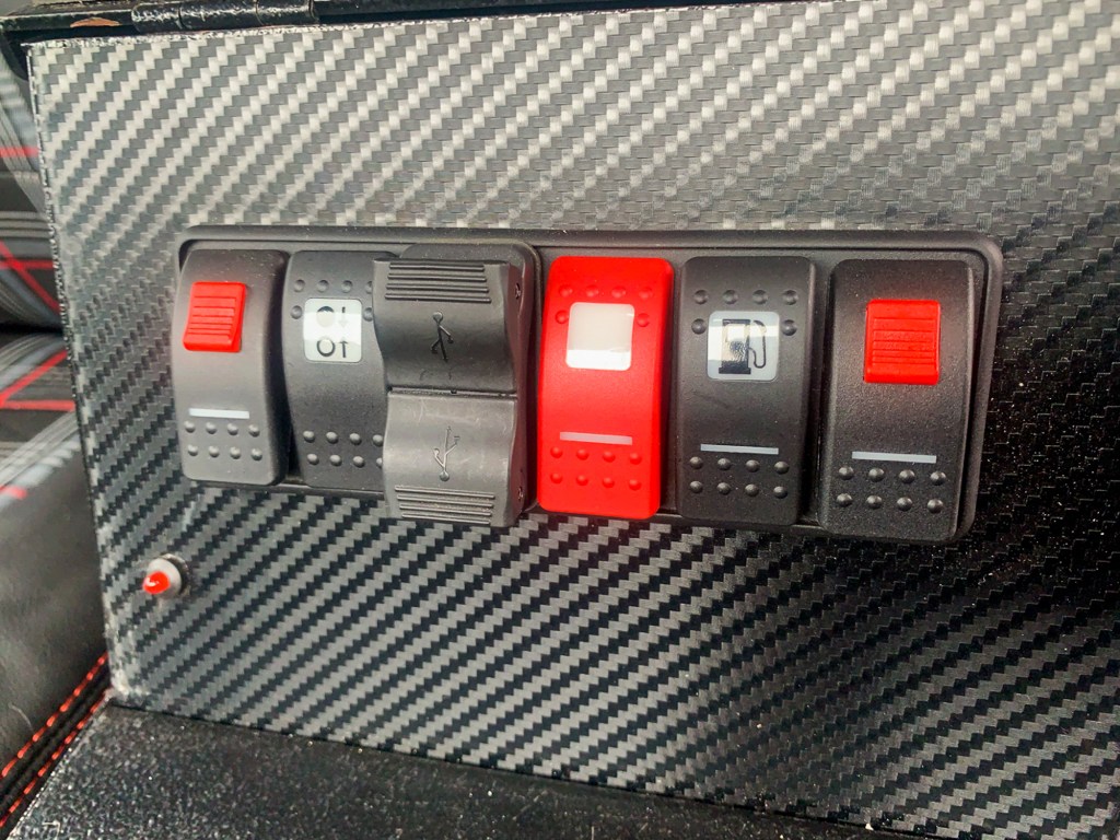
A similar wiring job was carried out in the front, adding circuits for the alarm, water heater, rear reversing light, fuel transfer between tanks, heater, a USB Charger and a spare!
The LED for the Alarm was added in the same location.
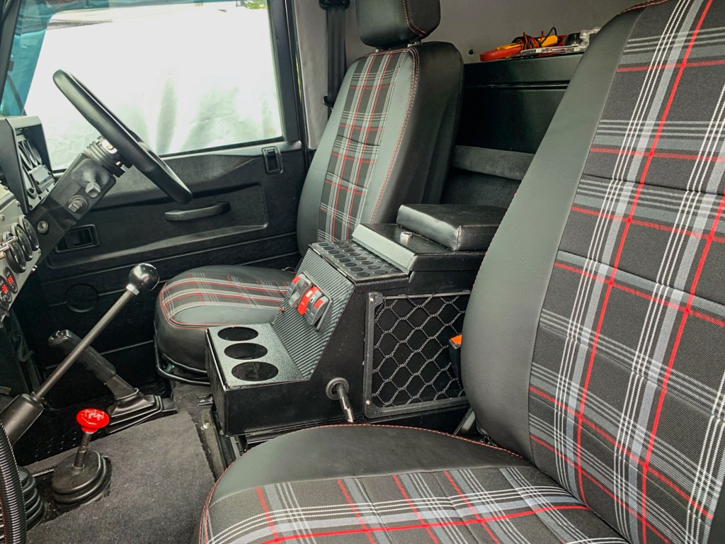
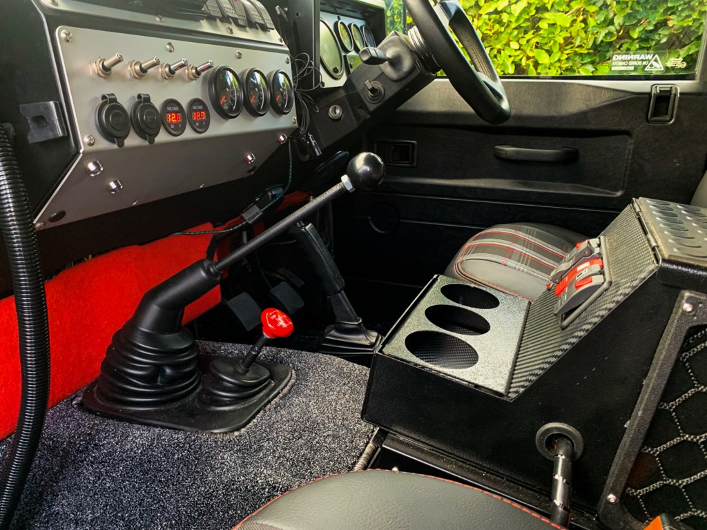
Centre Console Switches
Centre Console and Sub Woofer below.
Another job done, although it did take a couple of days to get it all working correctly.
Whilst I had spent time calculating power requirements, battery storage and the Watt hours that solar panels of various sizes can provide, this is at its very best, theoretical.
I only have so much room on my roof for solar panels I have no room to transport additional portable panels and only so much space to store batteries.
The runners for the roof bars restrict the width of the roof panels that I can install and I want to retain the ability to store some light stuff on the roof, at the front using roof bars (without casting a shadow on the panels and restricting power generation).
I also wanted flexible panels as these are lighter and can fix directly to the roof, thus keeping weight on the roof to a minimum, important as we have to lift it regularly to access the sleeping area.
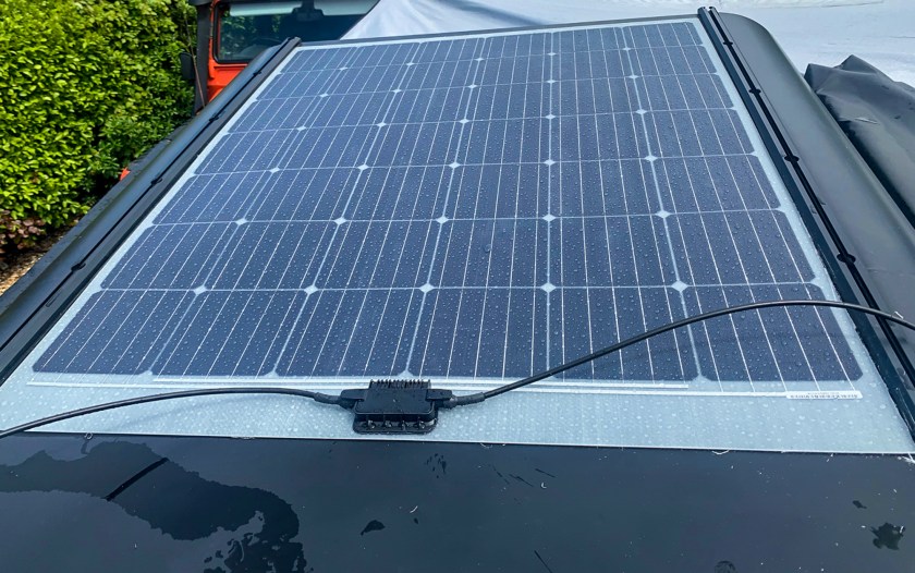
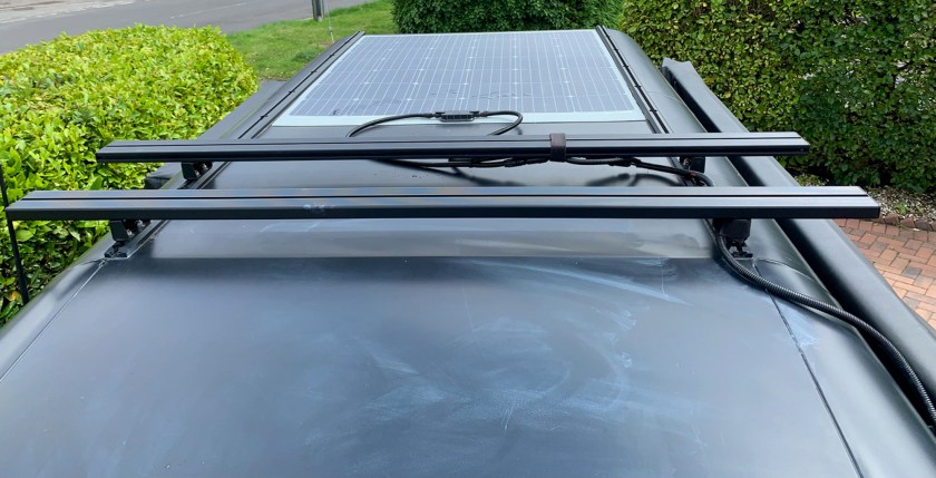
After the usual research, I found a 200w panel at Photonic Universe which fitted exactly between my roof bars and was self adhesive, so less messing around with sealant during installation. A bonus was that the panel was manufactured in Austria and not China!
The Solar Panel Installed
Wiring Block
The panel was installed with the wiring block towards the front, so that the cables can more easily be passed through to the interior. Strangley, some flexi panels have the wiring block in the back, so it pays to read the small print.
Next time I would get some help positioning the panel on the roof, as once the adhesive touches the surface, it is not going anywhere; I had to tale a small slice off of the right hand side just to make it fit correctly. I will add Sikaflex to the edges to ensure that water does not get underneatht the panel.
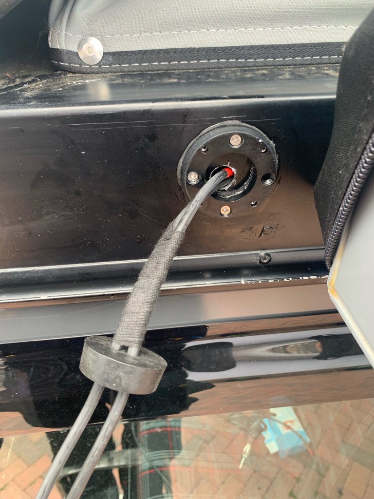
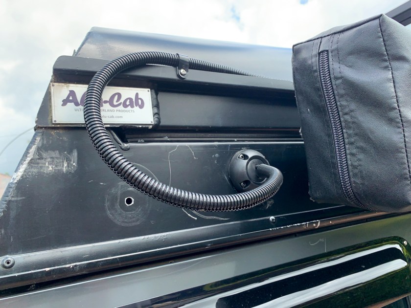
All that remains is to connect up the wiring and fit a Scan Strut waterproof grommet where the cable passes through the side of the roof.
Fitting the Scan Strut
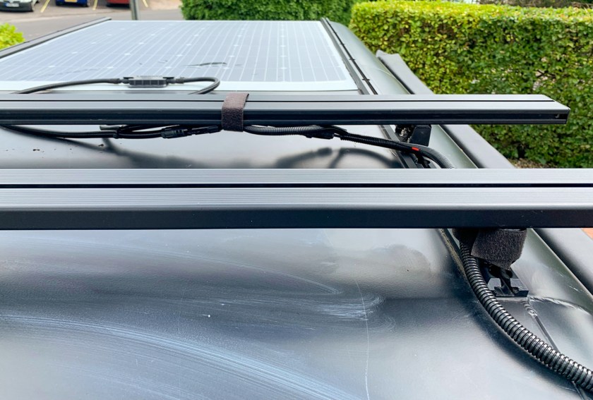
Then add some protection to the worres and we are all done. I will finally secure the wires to the roof bars once I know there final position.
The scratches on the paint were as a result of removing the front roof rack and will be sorted when the rack is re-fitted.
When we had the VW T25Camper, the electrics were rudimentary at the best and caused problems.
The Perentie will require much more power, so I spent a lot of time thinking about and calculating exactly what power would be required and how to store sufficient when we were off grid.
I am not going to cover the detail here as this has been done many time before and can be found easily on You Tube. However, it is not all correct………I would recommend Greg Virgo’s channel on You Tube. I will just explain what I did and why.
I do not want to carry gas as a permanent fixture, partly because I have no room, secondly and more importantly; I don’t like it from a safety point of view. Different fittings in different countries are a complication and I don’t want the hassle in the USA. A portable gas burner used whist in the UK, will be fine though, for occasional use.
So, I wanted enough power to be able to use a low powered kettle and induction hob, if not connected to the grid; even to save the cost of an electric hook up for an overnight stay. We would be driving most days, so keeping batteries charged should not be as issue, especially as I am planing solar as well.
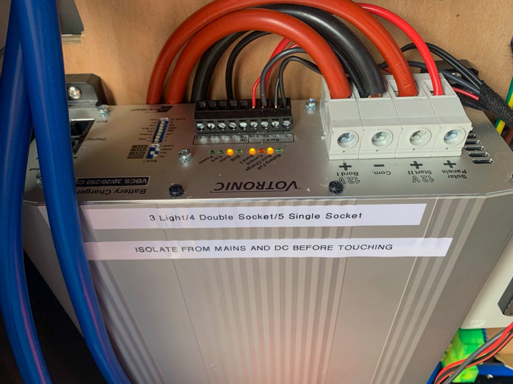
So the core of the system is a Votronic 3 way DC to DC charger which is a compact unit and negates the need for a separate Solar Controller. It will intelligently charge the leisure and starter batteries when the vehicle is running, from solar and from a 240v/110v supply when plugged in.
The Votronic DC to DC Charger.
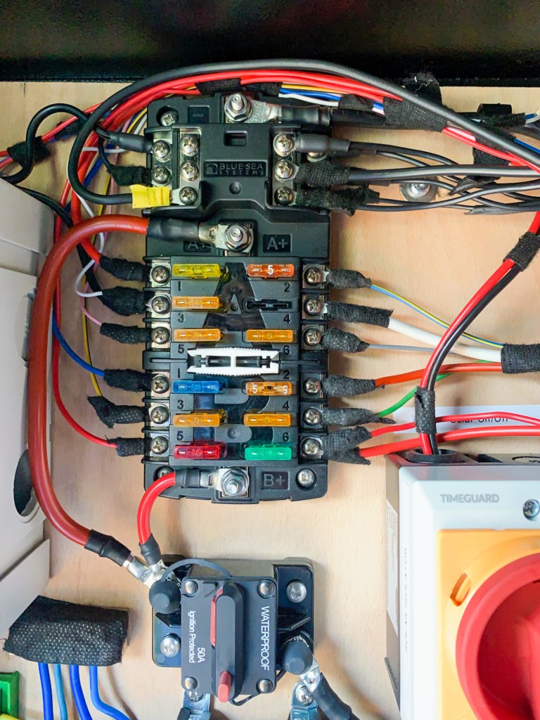
The 12v supply was easy. I used a Blue Sea fuse box with a common earth from the leisure batteries with a 50a breaker for protection. This gave me 12 x 12v circuits which was just enough. (I did have to double up on the LED lights, but these draw hardly any power).
12v Fuse Box & Breaker
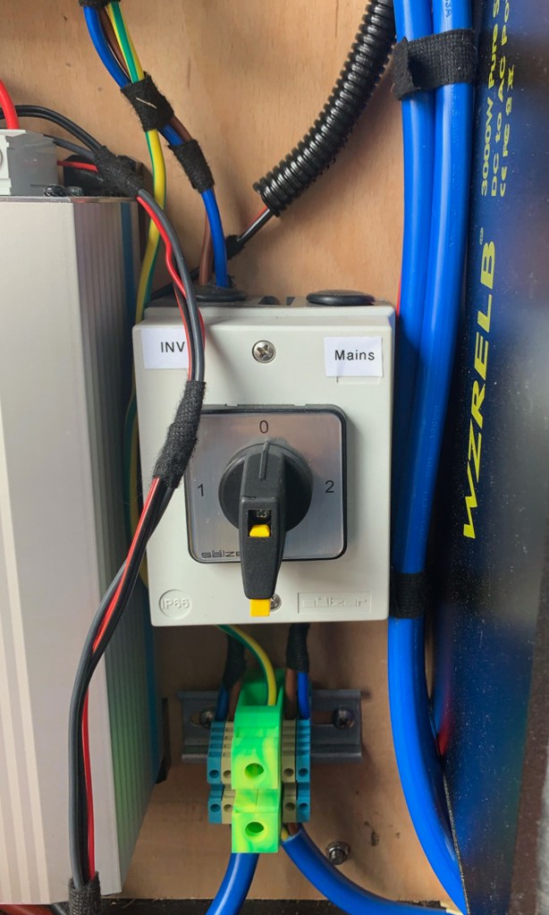
With the 240v, I wanted to be able to easily switch between mains (shore) power and the 240v supply that was being provided by the inverter when off-grid. Therefore having only one set of 240v wiring. I was only running three 240v circuits, one for a light, one for a double socket with USB points and one for the water heater (see separate post).
So I split the shore power coming in. One supply went to the Votronic Charger and another to a 2 Way double pole isolator switch.
Mains/Shore Power in.
The output from the inverter also went to the double pole isolator switch, so I could choose the source of my 240v supply. The output from the switch goes to a distribution board for the 3 x 240v circuits that have their own RCD. This means I can add more 240v circuits later , if needed.
Double Pole Isolater
RCD’s for the 240v Circuits
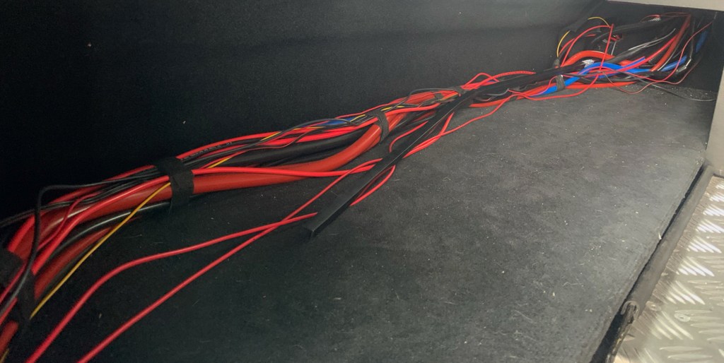
Thus all added up to quite a few wires. You have power in from the Solar which is fitted with an isolator as it is always live. Then power out to the starter and leisure batteries with an earth. Then you are feeding power back from the leisure batteries to the 12v fuse box and the inverter. The inverter is 3000w so a big cable with a 250w breaker. There are also a few wires for battery monitoring and others that I needed to run to the front of the vehicle, so I can switch them from there e.g. A rear light and the water heater.
The trail of wires
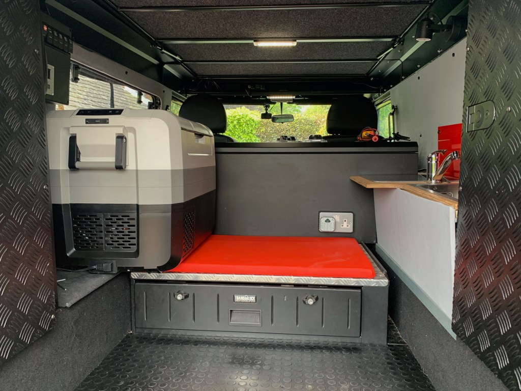
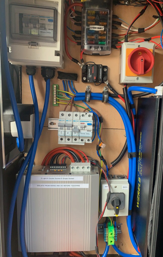
I fitted all of the electrics into a cabinet that we got with the vehicle, this was placed just inside the rear door, on the passenger side. I had previously run the wires that would need a 12v supply to this location.
The Power Board
The water will go in an identical cabinet on the drivers side.
Well, we were always going to need a heater and I must admit that I have been putting it off for a long time. But as the end of the build approaches, the job must be done.
Something always has to be last and in this case it is the heater, partly due to the cost, as it has to be professionally installed and partly, I was struggling to decide when to put the heating unit itself and the hot air outlets in the vehicle.
Early on, the thought process was, that if I put the heater in first, then it was bound to be in the wrong place. Leaving it until last, reduced the options for the installation and required a little ingenuity to get the thing fitted so it worked well, but in the end everything worked out.
Again a number of options for air heaters exist and it is easier to make a decision for an air heater, than for a water heater. Simply it had to be a diesel heater as I would always be carrying plenty of fuel for it. Eperspacher units seem to handle altitude better than Webasto, so that was the decision made.
I have mentioned Neil Read before in a few posts and I had already been in touch with Krueger a firm in New Milton that are Eperspacher installers. I did not realise initially that Krueger is opposite Neils workshop and that Neils son, Owen, works there……….
So when the Perentie was at Neils having the front roof rack sorted (Yes, in another post) we all met up and had a look at install options.
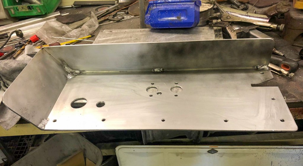
Not the easiest, but my suggestion that the heater unit was fitted on the chassis next to the second fuel tank was agreed upon. Owen figured the positions for the air intake and suggested solutions for two air outlets, one by the front passenger seat, slightly elevated and the second running towards the back of the vehicle to provide warm air at the back of the vehicle. Neil was happy to make a bracket to fix the heater to the chassis and to protect it from the elements.
I had already run a power supply from the main fusebox, so we were good to go.
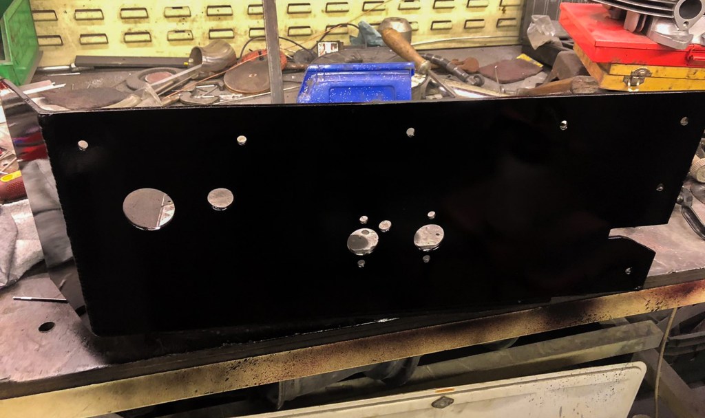
Heater bracket in the making.
Neil fitted the bracket, having already drilled the precise positions for the mountings and the outlets.
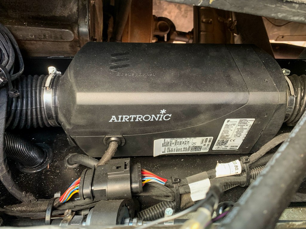
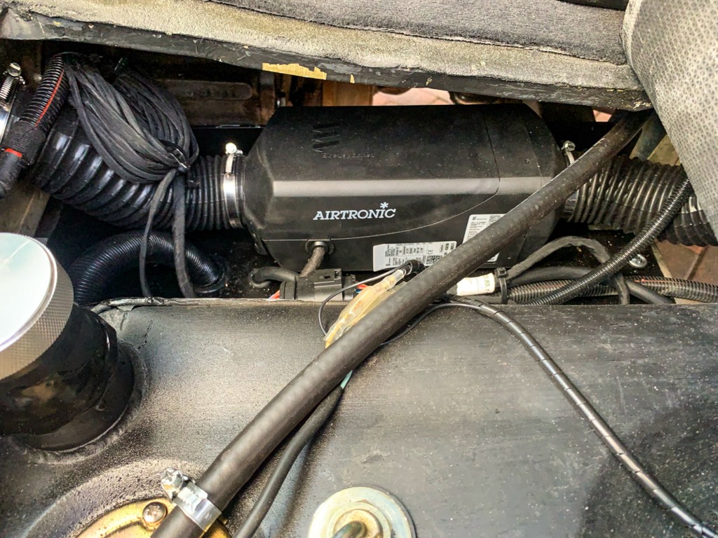
Over to Owen to fit the heater itself, the air intake, the outlets and the exhaust – this was positioned on the drivers side, well out of the way of the awning, which is on the passenger side.
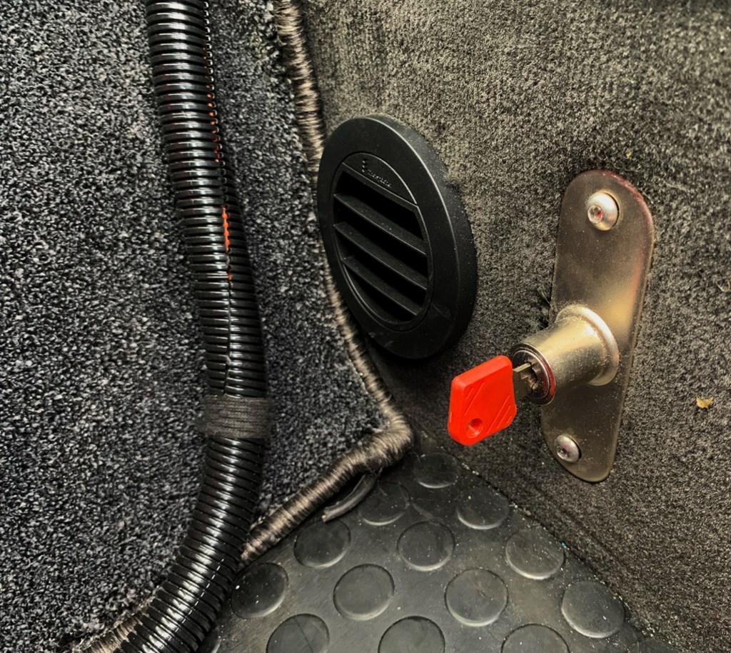
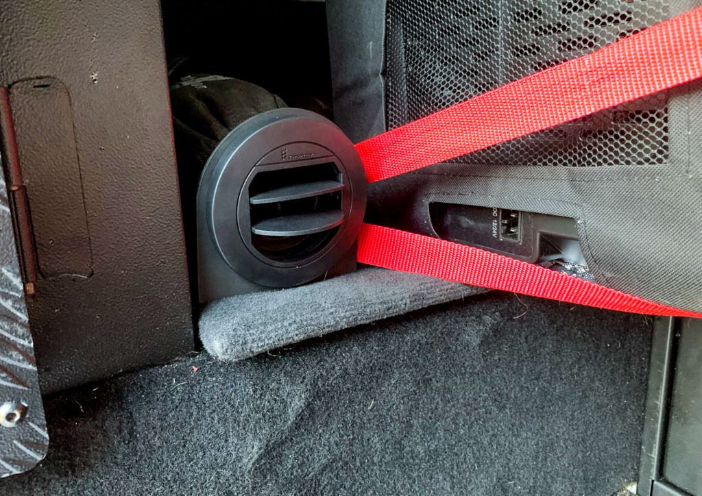
Heater in position
There was just enough room in the passenger footwell for the intake. Next to my newly made gearbox tunnel carpet!
Outlets are in the rear between the fridge and the electric cabinet and next to the passenger seat for heat to the front. Land Rover heaters are notoriously rubbish, so this will be a great addition to the vehicle and used daily in the Winter.
The next issue was where to position the (small) control panel. My plan originally was to be able to turn the unit on and off from a switch on the centre console and contol detailed options from the rear. However, in reality the unit needs constant power to retain its settings, so this was ruled out.
At the moment the panel is in the rear near to my main switch panel, good for camping, but awkward in the Winter when you just want to turn the heater on for everyday driving. I could move it to the front, but then, when camping, we can’t reach it.
There is (a very expensive) solution; the App – there is an app for everything……..But the app needs a module which also need a home and approx £500!
So at the time of writing the Jury is out…………………..